
TOUGHENING MODEL AND OPTIMIZATION CALCULATION FOR HIGH PERFORMANCE COMPOSITE BOX STRUCTURES
-
摘要:
为了深入揭示高性能箱型复合结构受力机理并有效提升结构整体性能,通过定义四种混凝土翼板模式开展高性能箱型复合结构增韧模型理论研究。通过建立剪力滞翘曲位移模型和界面滑移模式,推导出考虑剪力滞行为与界面滑移相互影响的控制微分方程,求得在均布荷载作用下的增韧模型理论解析解,进一步以界面滑移量、剪力滞系数、混凝土材料为韧性指标,对提出的增韧模型进行优化计算分析表明:II型增韧模型受剪力滞影响程度仅为0.04%~0.05%,混凝土材料用量节约35.00%,为四种模型中基于剪力滞与滑移耦合行为的最优高性能箱型复合结构增韧模型,便于为水利、土木工程韧性指标设计提供技术支撑。
Abstract:In order to further reveal the mechanical mechanism of high performance box composite structures and effectively improve their overall performances, four types of concrete wing modes were defined to carry out theoretical research on toughening model of high performance box composite structures. By establishing the shear-lag warpage displacement model and interfacial slip model, the governing differential equation was derived by considering the interaction between shear-lag behaviors and interfacial slips, and the theoretical analytical solution of the toughening model was obtained under uniformly distributed load. Further, with the interfacial slip, shear-lag coefficient and concrete material as the toughness indices, the optimization calculation and analysis of the proposed toughening model show that: Type II toughening model is only affected by shear lag by 0.04%-0.05%, and the concrete material consumption is reduced by 35.00%. It is the optimal high-performance box composite toughening model based on the coupled behaviors of shear lag and slip among the four models, which conveniently provides technical support for the design of toughness indices of water conservancy and civil engineering.
-
为纵深推动新阶段高质量发展,为满足结构服役能力向高要求、高标准的新时代发展需求,急需开发并研究承载能力高、跨越能力大、环境适应性好、安全保障完备的新型韧性结构,将有效弥补国家重大工程建设与发展短板。钢-混凝土复合结构作为一种新兴的高性能结构,兼具两种材料的优点,被大量运用于交通工程、桥梁工程、水利工程中,并取得了显著的经济和社会效益[1 − 2]。伴随着跨海大桥、大型场馆等超大型工程的建设,大跨度、大宽度仍然成为制约钢-混凝土复合结构成功运用的关键因素之一[3 − 4]。大量工程实践表明,钢-混凝土复合箱梁中存在的剪力滞效应和纵向界面滑移引起应力传递不均而导致结构发生翘曲变形甚至破坏,是另一大制约因素[5 − 6]。
对于钢-混凝土组合梁考虑剪力滞因素的研究,国内外众多学者做了大量的理论、试验与建模研究工作。孙飞飞等[7]、李法雄等[8]通过对I型钢截面组合梁建立纵向位移翘曲函数模型,进行了剪力滞效应的解析分析。随着组合箱梁研究的深入,程海根等[9]、何余良等[10]、朱力等[11]对考虑剪力滞效应的钢-混凝土组合箱梁通过不同的形函数模式,进行了解析解、有限元模型建立及室内试验研究。胡少伟等[12 − 13]根据双箱组合梁的结构特征建立抛物型纵向位移函数,基于最小势能原理得到了考虑剪滞效应的应力、应变解析表达式,从模型试验、数值建模对其进行了深入的研究。文献[14 − 15]通过引入不同翘曲位移函数,对不同荷载作用下的单箱双室钢-混凝土组合梁进行了剪力滞分析。目前,对考虑剪力滞影响的组合梁结构的理论研究,主要集中在通过建立的位移翘曲模式进行应力-应变以及剪力滞系数的推导分析,并结合试验、有限元模拟加以对比研究,而没有对其进行综合考虑材料属性、剪力滞空间分布特性的研究工作[16 − 18]。
为了探析剪力滞行为和界面滑移在高性能箱型复合结构增韧模型中的产生机理及结构空间韧性分布特性,定义四种不同混凝土翼板模式,建立剪力滞翘曲位移模型和界面滑移模式,推导增韧模型理论解析解,进行增韧模型优化计算分析。
1 高性能箱型复合结构增韧模型
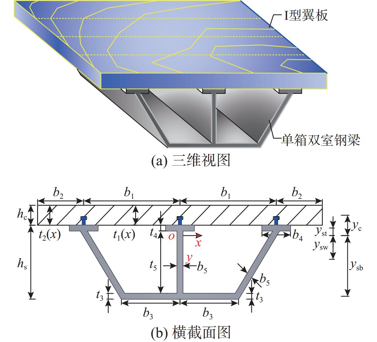
由大宽度混凝土翼板和单箱双室钢梁通过剪力连接件组合成的高性能箱型复合结构增韧模型,在进行增韧机理推导演算过程中,作如下基本假定:1)混凝土翼板与单箱双室钢梁相对滑移沿纵向方向呈均匀且连续分布;2)混凝土材料与钢材料均为线弹性材料;3)忽略混凝土板平面外的应变以及横向应变影响。
1.1 混凝土翼板模式
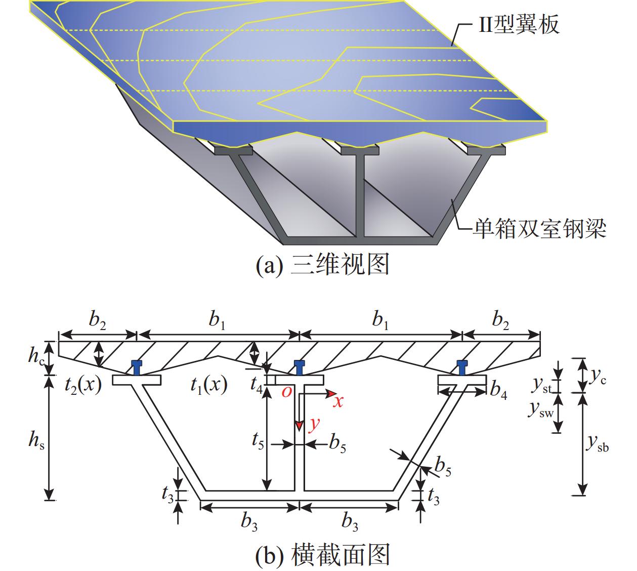
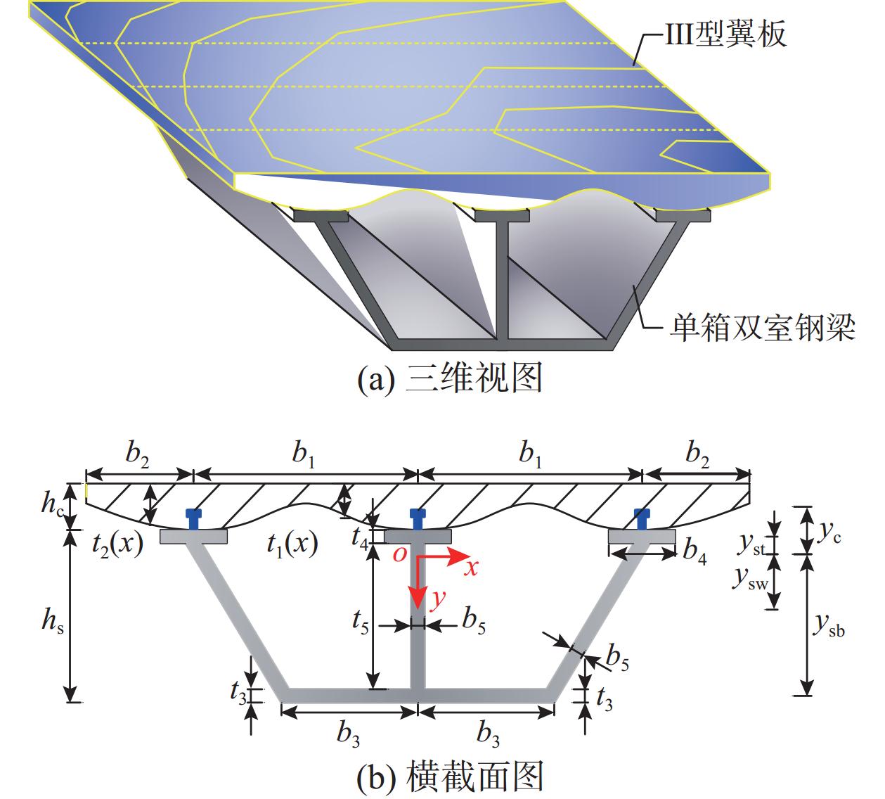
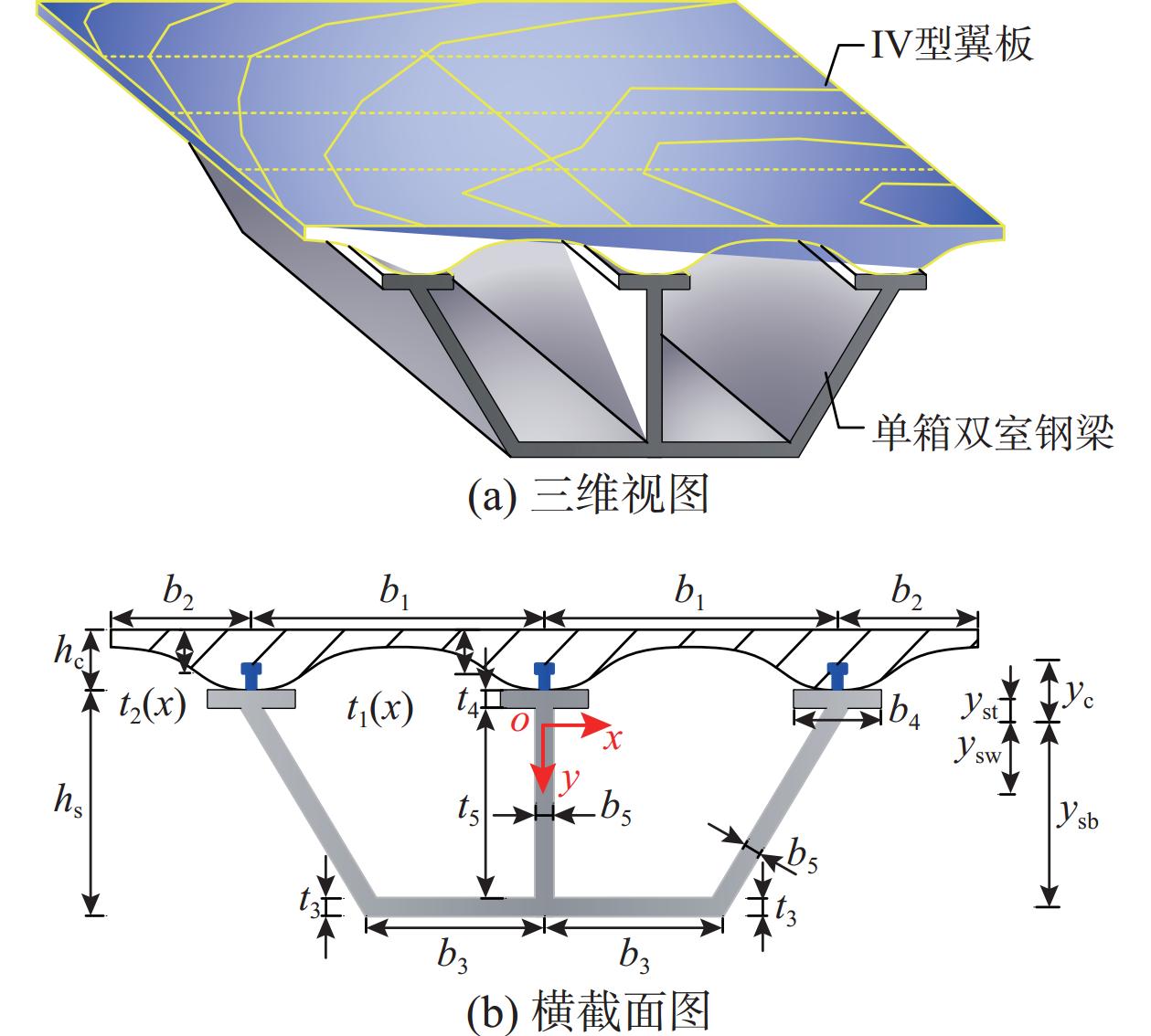
根据高性能箱型复合结构增韧模型特性,通过定义四种不同截面类型的混凝土翼板来开展该种结构的增韧特征研究。不同类型混凝土翼板所组成的四种高性能箱型复合结构增韧模型及其截面构造如图1~图4所示。
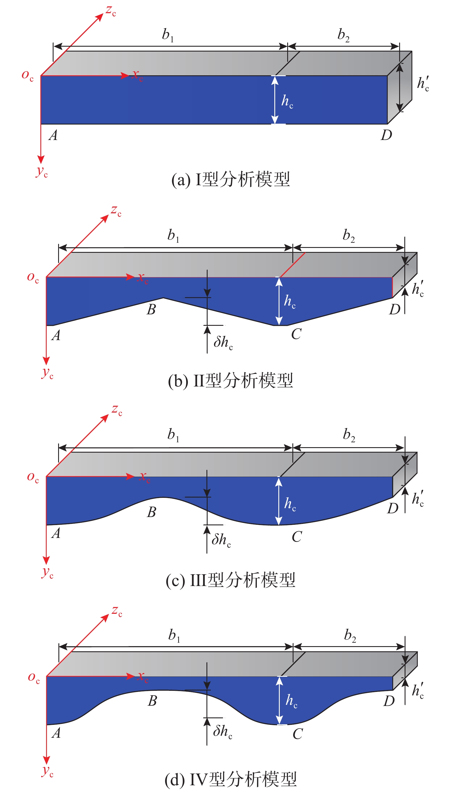
根据图5中I型、II型、III型、IV型四种类型横截面,分别建立混凝土翼板厚度计算公式t(i)j(x)(i=1,2,3,4;j=1,2):
{t(1)1(x)=h′c=hc,0<x⩽ (1) \left\{ \begin{aligned} & {t}_{\text{1}}^{\text{(2)}}(x)=\left\{ \begin{aligned} & -2{\mu }_{\text{h1}}x+{h}_{\text{c}},&&0 < x{\leqslant} 0.5{b}_{1}\\& 2{\mu }_{\text{h1}}x+{h}_{\text{c}}-2\delta {h}_{\text{c}},&&0.5{b}_{1} < x{\leqslant} {b}_{1} \end{aligned}\right.\text{;}\\& {t}_{\text{2}}^{\text{(2)}}(x)=-{\mu }_{\text{h2}}x+{h}_{\text{c}}+{\mu }_{\text{h2}}{b}_{1}, \;\;\;\;\;{b}_{1} < x{\leqslant} {b}_{1}+{b}_{2}. \end{aligned}\right. (2) \left\{ \begin{aligned} & {t}_{\text{1}}^{\text{(3)}}(x)=\left\{\begin{aligned} & -4{\mu }_{\text{hw1}}^{2}{x}^{2}+{h}_{\text{c}},&&0 < x{\leqslant} 0.5{b}_{1}\\& - 4\mu _{{\rm{hw1}}}^2{(x - {b_1})^2} + {h_{\rm{c}}},&&0.5{b}_{1} < x{\leqslant} {b}_{1} \end{aligned}\right.\text{;}\\& {t}_{\text{2}}^{\text{(3)}}(x)= - \mu _{{\rm{hw2}}}^2{(x - {b_1})^2} + {h_{\rm{c}}},\quad {b}_{1} < x{\leqslant} {b}_{1}+{b}_{2}. \end{aligned}\right. (3) \left\{\begin{aligned} & {t}_{\text{1}}^{\text{(4)}}(x)=4\mu _{{\rm{hw1}}}^2{(x - 0.5{b_1})^2} + {h'_{\rm{c}}},&& 0 < x{\leqslant} {b}_{1}\text{;}\\& {t}_{\text{2}}^{\text{(4)}}(x)=\mu _{{\rm{hw2}}}^2{(x - {b_1} - {b_2})^2} + {h'_{\rm{c}}},&&{b}_{1} < x{\leqslant} {b}_{1}\text+{b}_{2}. \end{aligned}\right. (4) 式中: \delta {h_{\text{c}}} = {h_{\text{c}}} - {h'_{\text{c}}} ; {\mu _{{\text{h1}}}} = b_1^{ - 1}\delta {h_{\text{c}}} ; {\mu _{{\text{h2}}}} = b_2^{ - 1}\delta {h_{\text{c}}} ; {\mu _{{\text{hw1}}}} = b_1^{ - 1}\sqrt {\delta {h_{\text{c}}}} ; {\mu _{{\text{hw2}}}} = b_2^{ - 1}\sqrt {\delta {h_{\text{c}}}} 。
将式(1)~式(4)代入,计算四种模式混凝土翼板截面面积 A_{\text{c}}^{{{(i)}}} :
A_{\text{c}}^{{{(i)}}} = 2\left[\int_0^{{b_{\text{1}}}} t_{\text{1}}^{{{(i)}}}(x){\text{d}}x + \int_{{b_{\text{1}}}}^{{b_{\text{1}}} + {b_{\text{2}}}} {t_{\text{2}}^{{{(i)}}}(x){\text{d}}x} \right] ,\;i{\text{ = 1,2,3,4}} (5) 进一步可求得横截面惯性矩 I_{\text{c}}^{{{(i)}}} :
\begin{split} I_{\text{c}}^{{{(i)}}} = & 2\int_0^{{b_{\text{1}}}} {\int_0^{t_{\text{1}}^{{{(i)}}}(x)} {{{[t_{\text{1}}^{{{(i)}}}(x)]}^2}{\text{d}}x{\text{d}}y} } +\\& 2\int_{{b_1}}^{{b_1} + {b_2}} {\int_0^{t_{\text{2}}^{{{(i)}}}(x)} {{{[t_{\text{2}}^{{{(i)}}}(x)]}^2}{\text{d}}x{\text{d}}y} } ,\; i{\text{ = 1,2,3,4}} \end{split} (6) 1.2 翘曲位移增韧模式
根据高性能箱型复合结构增韧模型受力变形特征,在考虑界面相对滑移和剪力滞作用下,其翘曲位移增韧函数由纵向线性变形、剪力滞作用导致的纵向变形和界面滑移引起的变形3部分组成。
\begin{split} {u}_{{j}}^{{(i)}}(x,y,{\textit{z}})=& {y}_{{j}}^{{(i)}}[{\theta }_{{j}}^{{(i)}}({\textit{z}})+{f}_{{j}}^{{(i)}}(x){g}_{{j}}^{{(i)}}({\textit{z}})]+{k}_{{j}}^{{(i)}}{s}_{{j}}^{{(i)}}({\textit{z}})\;,\\& i=1,2,3,4;j=1,2,3,4,5 \end{split} (7) 式中: i(i = 1,2,3,4) 为四种不同分析模式; j(j = 1,2,3,4,5) 分别为混凝土顶翼板、悬翼板,以及双室钢梁底板、支托板和腹板5种类型组件;\theta _{{j}}^{{{(i)}}}({\textit{z}})为线性转角;f_{{j}}^{{{(i)}}}(x)为剪力滞分布函数;g_{{j}}^{{{(i)}}}({\textit{z}})为强度函数;s_{{j}}^{{{(i)}}}({\textit{z}})为界面滑移函数;k_{{j}}^{{{(i)}}}为刚度系数。
其中,剪力滞分布函数为:
\begin{split} & f_{\text{1}}^{{{(i)}}}(x) = 1 - [2b_{\text{1}}^{ - 1}(x - 0.5{b_{\text{1}}}){]^{\text{2}}} , \\& f_{\text{2}}^{{{(i)}}}(x) = 1 - [b_{\text{2}}^{ - 1}({b_1} + {b_2} - x){]^{\text{3}}} , \\& f_{\text{3}}^{{{(i)}}}(x) = 1 - [2b_{\text{3}}^{ - 1}(x - 0.5{b_{\text{3}}}){]^{\text{2}}} , f_{\text{4}}^{{{(i)}}}(x) = f_{\text{5}}^{{{(i)}}}(x) = 1 。 \end{split} 1.3 增韧模型微分控制方程
由式(7)分别对{\textit{z}}和x求偏导,得到任意一点的正应变 {\varepsilon }_{{j}}^{{(i)}}(x,y,{\textit{z}}) 和剪应变 {\gamma }_{{j}}^{{(i)}}(x,y,{\textit{z}}) 表达式:
\begin{split} & {\varepsilon }_{{j}}^{{(i)}}(x,y,{\textit{z}})={y}_{{j}}^{{(i)}}\left[\frac{\partial {\theta }_{{j}}^{{(i)}}({\textit{z}})}{\partial {\textit{z}}}+{f}_{{j}}^{{(i)}}(x)\frac{\partial {g}_{{j}}^{{(i)}}({\textit{z}})}{\partial {\textit{z}}}\right]+\\&\quad {k}_{{j}}^{{(i)}}(x,y)\frac{\partial {s}_{{j}}^{{(i)}}({\textit{z}})}{\partial {\textit{z}}} \;,\; i=1,2,3,4;j=1,2,3,4,5 \end{split} (8) \begin{split} & {\gamma }_{x{\textit{z}}{{j}}}^{{(i)}}(x,y,{\textit{z}})={y}_{{j}}^{{(i)}}{g}_{{j}}^{{(i)}}({\textit{z}})\frac{\partial {f}_{{j}}^{{(i)}}(x)}{\partial x}+\frac{\partial {k}_{{j}}^{{(i)}}(x,y)}{\partial x}{s}_{{j}}^{{(i)}}({\textit{z}})\;,\\&\qquad i=1,2,3,4;j=1,2,3,4,5 \end{split} (9) 高性能箱型复合结构增韧模型在受力变形过程中,其能量主要由变形势能、界面滑移导致的能量和外荷载势能3部分组成,其总势能可表达为:
\begin{split} {U}_{\text{T}}^{(i)}= &\sum _{j=1}^{5}{U}_{\text{T}j}^{(i)}=\frac{1}{2} \sum _{j=1}^{5} {\int }_{x} {\int }_{y} {\int }_{\textit{z}}t(j)\{{E}_{j}^{(i)}{[{\varepsilon }_{j}^{(i)}(x,y,{\textit{z}})]}^{2}+\\& {G}_{j}^{(i)}{[{\gamma}_{x{\textit{z}}{j}}^{(i)}(x,y,{\textit{z}})]}^{\text{2}}\}\text{d}x\text{d}y\text{d}{\textit{z}}+\\& \frac{1}{2}{ \sum _{j=1}^{5}{ {\int }_{x}{ {\int }_{y}{ {\int }_{\textit{z}}{k}_{j}^{(i)}{[{s}_{j}^{(i)}({\textit{z}})]}^{2}}}}\text{d}x\text{d}y\text{d}{\textit{z}}}-\\& { {\int }_{x}{ {\int }_{y}{ {\int }_{\textit{z}}{M}^{(i)}(x,y,{\textit{z}})\frac{{\partial }^{2}{w}^{(i)}({\textit{z}})}{\partial {{\textit{z}}}^{2}}}}}\text{d}x\text{d}y\text{d}{\textit{z}}\\[-1pt] \end{split} (10) 式中: t(j) 为分项系数,分别取值为2、2、2、3、3; E_{{j}}^{{{(i)}}} 、 G_{{j}}^{{{(i)}}} 分别为四种模式下不同组件的弹性模量和剪切模量。
依据最小势能原理,令式(10)的一阶变分为零( \delta U_{\text{T}}^{{(i)}} = 0 ),可得高性能箱型复合结构增韧模型的微分控制方程及其边界条件。
\begin{split} & a_{\text{0}}^{{(i)}}[{w^{{(i)}}}({\textit{z}})]'' + a_{\text{1}}^{{(i)}}[l_{\text{1}}^{{(i)}}({\textit{z}})]' + a_{\text{2}}^{{(i)}}[l_{\text{2}}^{{(i)}}({\textit{z}})]' +\\&\qquad a_{\text{3}}^{{(i)}}[{s^{{(i)}}}({\textit{z}})]' + {M^{{(i)}}}(x,y,{\textit{z}}) = 0 \end{split} (11) c_{\text{0}}^{{(i)}}[l_{\text{1}}^{{(i)}}({\textit{z}})]'' + c_{\text{1}}^{{(i)}}[l_{\text{1}}^{{(i)}}({\textit{z}})] + c_{\text{2}}^{{(i)}}[{w^{{(i)}}}({\textit{z}})]''' + c_{\text{3}}^{{(i)}}[{s^{{(i)}}}({\textit{z}})]'' = 0 (12) d_{\text{0}}^{{(i)}}[l_{\text{2}}^{{(i)}}({\textit{z}})]'' + d_{\text{1}}^{{(i)}}[l_{\text{2}}^{{(i)}}({\textit{z}})] + d_{\text{2}}^{{(i)}}[{w^{{(i)}}}({\textit{z}})]''' + d_{\text{3}}^{{(i)}}[{s^{{(i)}}}({\textit{z}})]'' = 0 (13) \begin{split} & e_{\text{0}}^{{(i)}}[{s^{{(i)}}}({\textit{z}})]'' + e_{\text{1}}^{{(i)}}[{s^{{(i)}}}({\textit{z}})] + e_{\text{2}}^{{(i)}}[{w^{{(i)}}}({\textit{z}})]''' +\\&\qquad e_{\text{3}}^{{(i)}}[l_{\text{1}}^{{(i)}}({\textit{z}})]'' + e_{\text{4}}^{{(i)}}[l_{\text{2}}^{{(i)}}({\textit{z}})]''\} = 0 \end{split} (14) \{ c_{\text{0}}^{{(i)}}[l_{\text{1}}^{{(i)}}({\textit{z}})]' + c_{\text{2}}^{{(i)}}[{w^{{(i)}}}({\textit{z}})]'' + c_{\text{3}}^{{(i)}}[{s^{{(i)}}}({\textit{z}})]\} \delta [l_{\text{1}}^{{(i)}}({\textit{z}})]\left| {_0^{{L_0}}} \right. = 0 (15) \{ d_{\text{0}}^{{(i)}}[l_{\text{2}}^{{(i)}}({\textit{z}})]' + d_{\text{2}}^{{(i)}}[{w^{{(i)}}}({\textit{z}})]'' + d_{\text{3}}^{{(i)}}[{s^{{(i)}}}({\textit{z}})]'\} \delta [l_{\text{2}}^{{(i)}}({\textit{z}})]\left| {_0^{{L_0}}} \right. = 0 (16) \begin{split} & \{ e_{\text{0}}^{{(i)}}[{s^{{(i)}}}({\textit{z}})]' + e_{\text{2}}^{{(i)}}[{w^{{(i)}}}({\textit{z}})]'' + e_{\text{3}}^{{(i)}}[l_{\text{1}}^{{(i)}}({\textit{z}})]' +\\&\qquad e_{\text{4}}^{{(i)}}[l_{\text{2}}^{{(i)}}({\textit{z}})]'\} \delta [{s^{{(i)}}}({\textit{z}})]\left| {_0^{{L_0}}} \right. = 0 \end{split} (17) 式中:
\begin{split} & l_{\text{1}}^{{(i)}}({\textit{z}}) = g_{\text{1}}^{{(i)}}({\textit{z}}) = g_{\text{2}}^{{(i)}}({\textit{z}}) ;\\[-2pt]& l_{\text{2}}^{{(i)}}({\textit{z}}) = g_{\text{3}}^{{(i)}}({\textit{z}}) = g_{\text{4}}^{{(i)}}({\textit{z}}) = g_{\text{5}}^{{(i)}}({\textit{z}}) ;\\[-2pt]& a_{\text{0}}^{{(i)}} = \sum\limits_{j = 1}^5 {\iint\limits_{xy} {t(j)E_{j}^{{(i)}}{{[y_{j}^{{(i)}}]}^2}{\text{d}}x{\text{d}}y}} ;\\[-2pt]&a_{\text{1}}^{{(i)}} = 2\sum\limits_{j = 1}^2 {\iint\limits_{xy} {t(j)E_{j}^{{(i)}}{{[y_{j}^{{(i)}}]}^2}f_{j}^{{(i)}}(x){\text{d}}x{\text{d}}y}} ;\\[-2pt]& a_{\text{2}}^{{(i)}} = 2\sum\limits_{j = 3}^5 {\iint\limits_{xy} {t(j)E_{j}^{{(i)}}{{[y_{j}^{{(i)}}]}^2}f_{j}^{{(i)}}(x){\text{d}}x{\text{d}}y}} ;\\[-2pt]& a_{\text{3}}^{{(i)}} = 2\sum\limits_{j = 1}^5 {\iint\limits_{xy} {t(j)E_{j}^{{(i)}}y_{j}^{{(i)}}k_{j}^{{(i)}}(x,y){\text{d}}x{\text{d}}y}} ;\\[-2pt]&c_{\text{0}}^{{(i)}} = - \frac{1}{2}\sum\limits_{j = 1}^2 {\iint\limits_{xy} {t(j)E_{j}^{{(i)}}{{[y_{j}^{{(i)}}f_{j}^{{(i)}}(x)]}^2}{\text{d}}x{\text{d}}y}} ;\\[-2pt]&c_{\text{1}}^{{(i)}} = \sum\limits_{j = 1}^2 {\iint\limits_{xy} {t(j)G_{j}^{{(i)}}{{[y_{j}^{{(i)}}]}^2}{{\{ [f_{j}^{{(i)}}(x)]'\} }^2}{\text{d}}x{\text{d}}y}} ;\\[-2pt]& c_{\text{2}}^{{(i)}} = - \sum\limits_{j = 1}^2 {\iint\limits_{xy} {t(j)E_{j}^{{(i)}}{{[y_{j}^{{(i)}}]}^2}f_{j}^{{(i)}}(x){\text{d}}x{\text{d}}y}} ;\\[-2pt]& c_{\text{3}}^{{(i)}} = - \sum\limits_{j = 1}^2 {\iint\limits_{xy} {t(j)E_{j}^{{(i)}}y_{j}^{{(i)}}f_{j}^{{(i)}}(x)k_{j}^{{(i)}}(x,y){\text{d}}x{\text{d}}y}} ;\\[-2pt]& d_{\text{0}}^{{(i)}} = - \frac{1}{2}\sum\limits_{j = 3}^5 {\iint\limits_{xy} {t(j)E_{j}^{{(i)}}{{[y_{j}^{{(i)}}f_{j}^{{(i)}}(x)]}^2}{\text{d}}x{\text{d}}y}} ;\\[-2pt]& d_{\text{1}}^{{(i)}} = \sum\limits_{j = 3}^5 {\iint\limits_{xy} {t(j)G_{j}^{{(i)}}{{[y_{j}^{{(i)}}]}^2}{{\{ [{f_{j}}(x)]'\} }^2}{\text{d}}x{\text{d}}y}} ;\\[-2pt]& d_{\text{2}}^{{(i)}} = - \sum\limits_{j = 3}^5 {\iint\limits_{xy} {t(j)E_{j}^{{(i)}}{{[y_{j}^{{(i)}}]}^2}f_{j}^{{(i)}}(x){\text{d}}x{\text{d}}y}} ;\\[-2pt]& d_{\text{3}}^{{(i)}} = - \sum\limits_{j = 3}^5 {\iint\limits_{xy} {t(j)E_{j}^{{(i)}}y_{j}^{{(i)}}f_{j}^{{(i)}}(x)k_{j}^{{(i)}}(x,y){\text{d}}x{\text{d}}y}} ;\\[-2pt]& e_{\text{0}}^{{(i)}} = - \frac{1}{2}\sum\limits_{j = 3}^5 {\iint\limits_{xy} {t(j)E_{j}^{{(i)}}{{[k_{j}^{{(i)}}(x,y)]}^2}{\text{d}}x{\text{d}}y}} ;\\[-2pt]& e_{\text{1}}^{{(i)}} = \sum\limits_{j = 1}^5 {\iint\limits_{xy} {K_{j}^{{(i)}}{\text{d}}x{\text{d}}y}} ;\\[-2pt]& e_{\text{2}}^{{(i)}} = - \sum\limits_{j = 1}^5 {\iint\limits_{xy} {t(j)E_{j}^{{(i)}}y_{j}^{{(i)}}k_{j}^{{(i)}}(x,y){\text{d}}x{\text{d}}y}} ;\\[-2pt]& e_{\text{3}}^{{(i)}} = - \sum\limits_{j = 1}^2 {\iint\limits_{xy} {t(j)E_{j}^{{(i)}}y_{j}^{{(i)}}f_{j}^{{(i)}}(x)k_{j}^{{(i)}}(x,y){\text{d}}x{\text{d}}y}} ;\\[-2pt]& e_{\text{4}}^{{(i)}} = - \sum\limits_{j = 3}^5 {\iint\limits_{xy} {t(j)E_{j}^{{(i)}}y_{j}^{{(i)}}f_{j}^{{(i)}}(x)k_{j}^{{(i)}}(x,y){\text{d}}x{\text{d}}y}} 。 \end{split} 2 增韧模型理论解析解
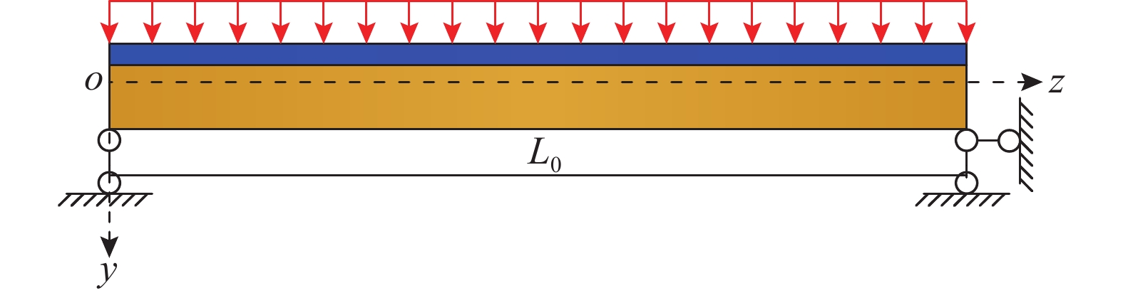
图6中给定了在均布荷载q作用下的高性能箱型复合结构增韧模型示意图,可得任意截面的剪力和弯矩为:
V({\textit{z}}) = 0.5({L_0} - 2{\textit{z}})q (18) M({\textit{z}}) = 0.5\textit{z}({L_0} - {\textit{z}})q (19) 2.1 基于界面滑移函数的韧性解析解
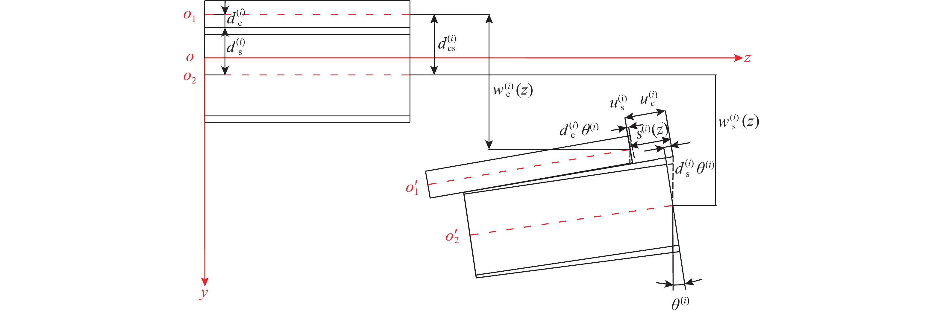
根据基本假定条件1,建立混凝土翼板与单箱双室钢梁界面滑移分析模型,如图7所示。
单箱双室钢梁和混凝土翼板的弯矩和内力分别表达为:
M_{\text{c}}^{{{(i)}}} = d_{\text{c}}^{{{(i)}}}E_{\text{c}}^{{{(i)}}}A_{\text{c}}^{{{(i)}}}[w_{\text{c}}^{{{(i)}}}({\textit{z}})]' + E_{\text{c}}^{{{(i)}}}I_{\text{c}}^{{{(i)}}}[\theta _{\text{c}}^{(i)}{({\textit{z}})}]' (20) M_{\text{s}}^{{{(i)}}} = d_{\text{s}}^{{{(i)}}}E_{\text{s}}^{{{(i)}}}A_{\text{s}}^{{{(i)}}}[{w_{\text{s}}}({\textit{z})}]' + E_{\text{s}}^{{{(i)}}}I_{\text{s}}^{{{(i)}}}[\theta _{\text{s}}^{{{(i)}}}{({\textit{z}})}]' (21) N_{\text{c}}^{{{(i)}}} = E_{\text{c}}^{{{(i)}}}A_{\text{c}}^{{{(i)}}}\{ [w_{\text{c}}^{{{(i)}}}({\textit{z}})]' + d_{\text{c}}^{{{(i)}}}[\theta _{\text{c}}^{{{(i)}}}{({\textit{z}})}]'\} (22) N_{\text{s}}^{{{(i)}}} = - E_{\text{s}}^{{{(i)}}}A_{\text{s}}^{{{(i)}}}\{ [{w_{\text{s}}}({\textit{z}})]' - d_{\text{s}}^{{{(i)}}}[\theta _{\text{s}}^{{{(i)}}}{({\textit{z}})}]'\} (23) 式中: d_{\text{c}}^{{{(i)}}} = \alpha _{\text{E}}^{{{(i)}}}A_{\text{s}}^{{{(i)}}}{[\alpha _{\text{E}}^{{{(i)}}}A_{\text{s}}^{{{(i)}}} + A_{\text{c}}^{{{(i)}}}]^{ - 1}}d_{{\text{cs}}}^{{{(i)}}} ; d_{\text{s}}^{{{(i)}}} = A_{\text{c}}^{{{(i)}}}[\alpha _{\text{E}}^{{{(i)}}}A_{\text{s}}^{{{(i)}}} + A_{\text{c}}^{{{(i)}}}]^{ - 1}d_{{\text{cs}}}^{{{(i)}}} , \alpha _{\text{E}}^{{{(i)}}} = {[E_{\text{c}}^{{{(i)}}}]^{ - 1}}E_{\text{s}}^{{{(i)}}} ; d_{{\text{cs}}}^{{{(i)}}} = d_{\text{c}}^{{{(i)}}} + d_{\text{s}}^{{{(i)}}} 。
根据轴力内力平衡条件 N_{\text{c}}^{{{(i)}}} + N_{\text{s}}^{{{(i)}}} = 0 ,将 \dfrac{{\partial w_{\text{c}}^{{{(i)}}}({\textit{z}})}}{{\partial {\textit{z}}}} = d_{\text{c}}^{{{(i)}}}{[d_{{\text{cs}}}^{{{(i)}}}]^{ - 1}}[{s^{{{(i)}}}}({\textit{z}})]' 和 \dfrac{{\partial w_{\text{s}}^{{{(i)}}}({\textit{z}})}}{{\partial {\textit{z}}}} = - d_{\text{s}}^{{{(i)}}}{[d_{{\text{cs}}}^{{{(i)}}}]^{ - 1}}[{s^{{{(i)}}}}({\textit{z}})]' 代入式(22)和式(23),可得:
N_{\text{c}}^{{{(i)}}} = - N_{\text{s}}^{{{(i)}}} = [{E^{{{(i)}}}}{A^{{{(i)}}}}]\{ [{s^{{{(i)}}}}({\textit{z}})]' + d_{{\text{cs}}}^{{{(i)}}}[{\theta ^{{{(i)}}}}({\textit{z}})]'\} (24) 式中, {[{E^{{{(i)}}}}{A^{{{(i)}}}}]^{ - 1}} = {[E_{\text{c}}^{{{(i)}}}A_{\text{c}}^{{{(i)}}}]^{ - 1}} + {[E_{\text{s}}^{{{(i)}}}A_{\text{s}}^{{{(i)}}}]^{ - 1}} 。
将 \dfrac{{\partial w_{\text{c}}^{{{(i)}}}({\textit{z}})}}{{\partial {\textit{z}}}} = d_{\text{c}}^{{{(i)}}}{[d_{{\text{cs}}}^{{{(i)}}}]^{ - 1}}[{s^{{{(i)}}}}({\textit{z}})]' 和 \dfrac{{\partial w_{\text{s}}^{{{(i)}}}({\textit{z}})}}{{\partial {\textit{z}}}} = d_{\text{s}}^{{{(i)}}}{[d_{{\text{cs}}}^{{{(i)}}}]^{ - 1}}[{s^{{{(i)}}}}({\textit{z}})]' 代入式(20)和式(21),可得单箱双室组合梁的总弯矩为:
{M^{{{(i)}}}} = {d_{{\text{cs}}}}[{E^{{{(i)}}}}{A^{{{(i)}}}}][{s^{{{(i)}}}}({\textit{z}})]' + E_0^{^{{{(i)}}}}I_0^{^{{{(i)}}}}[{\theta ^{{{(i)}}}}{({\textit{z}})}]' (25) 式中, E_0^{^{{{(i)}}}}I_0^{^{{{(i)}}}} = E_{\text{c}}^{{{(i)}}}I_{\text{c}}^{{{(i)}}} + E_{\text{s}}^{{{(i)}}}I_{\text{s}}^{{{(i)}}} 。
根据剪应力传递条件 \dfrac{{\partial N_{\text{c}}^{{{(i)}}}}}{{\partial {\textit{z}}}} - {T^{{{(i)}}}} = 0 ,将式(24)和 {T^{{{(i)}}}} = {K^{{{(i)}}}}{s^{{{(i)}}}}({\textit{z}}) 代入,可得:
[{E^{{{(i)}}}}{A^{{{(i)}}}}]\{ [{s^{{{(i)}}}}({\textit{z}})]'' + d_{{\text{cs}}}^{{{(i)}}}[{\theta ^{{{(i)}}}}{\text{(z}})]''\} - {K^{{{(i)}}}}{s^{{{(i)}}}}({\textit{z}}) = 0 (26) 根据剪力平衡条件 \dfrac{{\partial {M^{{{(i)}}}}({\textit{z}})}}{{\partial {\textit{z}}}} - {V^{{{(i)}}}}({\textit{z}}) = 0 ,将式(25)代入可得:
{V^{{{(i)}}}}({\textit{z}}) = {d_{{\text{cs}}}}[{E^{{{(i)}}}}{A^{{{(i)}}}}][{s^{{{(i)}}}}({\textit{z}})]'' + E_0^{^{{{(i)}}}}I_0^{^{{{(i)}}}}[{\theta ^{{{(i)}}}}{({\textit{z}})}]'' (27) 将式(27)代入式(26)可得界面滑移方程:
[{s^{{{(i)}}}}({\textit{z}})]'' - {[\pi _0^{{{(i)}}}]^2}{s^{{{(i)}}}}({\textit{z}}) + {[{E^{{{(i)}}}}{I^{{{(i)}}}}]^{ - 1}}d_{{\text{cs}}}^{{{(i)}}}{V^{{{(i)}}}}({\textit{z}}) = 0 (28) 式中: {E^{{{(i)}}}}{I^{{{(i)}}}} = E_0^{^{{{(i)}}}}I_0^{^{{{(i)}}}} - {[d_{{\text{cs}}}^{{{(i)}}}]^2}[{E^{{{(i)}}}}{A^{{{(i)}}}}] ; {[\pi _0^{{{(i)}}}]^2} = {K^{{{(i)}}}}E_0^{^{{{(i)}}}}I_0^{^{{{(i)}}}} {[{E^{{{(i)}}}}{I^{{{(i)}}}}]^{ - 1}}{[{E^{{{(i)}}}}{A^{{{(i)}}}}]^{ - 1}} 。
将边界条件 [{s^{{{(i)}}}}({\textit{z}} = 0)]' = 0 和 [{s^{{{(i)}}}}({\textit{z}} = {L_0})]' = 0 代入,计算得四种分析模式下高性能箱型复合结构增韧模型在均布荷载作用下的界面滑移函数 {s^{{{(i)}}}}({\textit{z}}) 为:
{s^{{{(i)}}}}({\textit{z}}) = - {\overline \pi ^{{{(i)}}}}q[\sinh (\pi _0^{{{(i)}}}{\textit{z}}) - \pi _1^{{{(i)}}}\cosh ({\pi _0}{\textit{z}}) + \pi _0^{{{(i)}}}(0.5{L_0} - {\textit{z}})] (29) 式中: \pi _1^{{{(i)}}} = {\sinh ^{ - 1}}(\pi _0^{{{(i)}}}{L_0})[\cosh (\pi _0^{{{(i)}}}{L_0}) - 1] ; {\overline \pi ^{{{(i)}}}} = d_{{\text{cs}}}^{{{(i)}}}{[{K^{{{(i)}}}}]^{ - 1}}{[\pi _0^{{{(i)}}}]^{ - 1}}{[E_0^{^{{{(i)}}}}I_0^{^{{{(i)}}}}]^{ - 1}}[{E^{{{(i)}}}}{A^{{{(i)}}}}] 。
抗剪刚度系数 {K^{{{(i)}}}} 由下式来计算[19]。
V_{{\text{ud}}}^{{{{(i)}}}} = 0.43A_{\text{d}}^{^{{{(i)}}}}\sqrt {{E_{\text{c}}}{f_{\text{c}}}} (30) {K^{{{(i)}}}} = 0.66V_{{\text{ud}}}^{{{{(i)}}}} (31) 式中: A_{\text{d}}^{^{{{(i)}}}} = {[d_{\text{d}}^{^{{{(i)}}}}]^2}/4 ; d_{\text{d}}^{^{{{(i)}}}} 为栓钉直径; {E_{\text{c}}} 和 {f_{\text{c}}} 分别为混凝土弹性模量和轴心抗压强度标准值。
2.2 基于剪力滞系数的韧性解析解
将式(11)~式(13)、式(29)代入强度函数的边界条件等式 l_{\text{1}}^{{{(i)}}}({\textit{z}})\left| {_{{\textit{z}} = 0}} \right. = l_{\text{2}}^{{{(i)}}}({\textit{z}})\left| {_{{\textit{z}} = 0}} \right. = 0 , [l_{\text{1}}^{{{(i)}}}({\textit{z}})]'\left| {_{{\textit{z}} =0.5{L_0}}} \right. = [l_{\text{2}}^{{{(i)}}}({\textit{z}})]'\left| {_{{\textit{z}} = 0.5{L_0}}} \right. = 0 ,求得:
\begin{split} & l_{\text{1}}^{{{(i)}}}({\textit{z}}) = \kappa _{\text{1}}^{{{(i)}}}\{ D_{\text{1}}^{{{(i)}}}{\text{sinh(}}{\varpi ^{{{(i)}}}}{{{\textit{z}}) + }}D_{\text{2}}^{{{(i)}}}{\text{cosh(}}{\varpi ^{{{(i)}}}}{{{\textit{z}})}} +\\&\;\;\;\; \theta _{\text{1}}^{{{(i)}}}[{\text{sinh(}}\pi _{\text{0}}^{{{(i)}}}{{{\textit{z}}) - }}\pi _{\text{1}}^{{{(i)}}}{\text{cosh(}}\pi _{\text{0}}^{{{(i)}}}{{{\textit{z}})}}] + \theta _{\text{2}}^{{{(i)}}}({\textit{z}} - 0.5{L_0})\} \end{split} (32) \begin{split} & l_{\text{2}}^{{{(i)}}}({\textit{z}}) = \kappa _{\text{2}}^{{{(i)}}}\{ D_{\text{1}}^{{{(i)}}}{\text{sinh(}}{\varpi ^{{{(i)}}}}{{{\textit{z}}) + }}D_{\text{2}}^{{{(i)}}}{\text{cosh(}}{\varpi ^{{{(i)}}}}{{{\textit{z}})}} + \\& \theta _{\text{1}}^{{{(i)}}}[{\text{sinh(}}\pi _{\text{0}}^{{{(i)}}}{{{\textit{z}}) - }}\pi _{\text{1}}^{{{(i)}}}{\text{cosh(}}\pi _{\text{0}}^{{{(i)}}}{{{\textit{z}})}}] + \theta _{\text{2}}^{{{(i)}}}({\textit{z}} - 0.5{L_0})\} \end{split} (33) 式中:
\begin{split} & \kappa _{\text{1}}^{{{(i)}}} = c_{\text{2}}^{{{(i)}}}e_{\text{2}}^{{{(i)}}}(a_{\text{3}}^{{{(i)}}} + c_{\text{0}}^{{{(i)}}} - c_{\text{3}}^{{{(i)}}}){[a_{\text{0}}^{{{(i)}}}]^{ - 1}}{[{\varpi ^{{{(i)}}}}]^2} ;\\[-2pt]& \kappa _{\text{2}}^{{{(i)}}} = - \gamma _{\text{2}}^{{{(i)}}}\eta _{\text{4}}^{{{(i)}}}(2\alpha _{\text{3}}^{{{(i)}}} + \eta _{\text{0}}^{{{(i)}}} - \eta _{\text{3}}^{{{(i)}}}){[\alpha _{\text{0}}^{{{(i)}}}]^{ - 1}}{[{\varpi ^{{{(i)}}}}]^2} ;\\[-2pt]& {\varpi ^{{{(i)}}}} = {[a_{\text{0}}^{{{(i)}}}c_{\text{1}}^{{{(i)}}}]^{0.5}}{[a_{\text{0}}^{{{(i)}}}c_{\text{1}}^{{{(i)}}} - (a_{\text{1}}^{{{(i)}}} + a_{\text{2}}^{{{(i)}}})c_{\text{2}}^{{{(i)}}}]^{ - 0.5}} ;\\[-2pt]& \theta _{\text{1}}^{{{(i)}}} = (a_{\text{0}}^{{{(i)}}}c_{\text{3}}^{{{(i)}}} + a_{\text{3}}^{{{(i)}}}c_{\text{2}}^{{{(i)}}})\{ (a_{\text{1}}^{{{(i)}}} + a_{\text{2}}^{{{(i)}}})c_{\text{2}}^{{{(i)}}} -\\[-2pt]&\qquad a_{\text{0}}^{{{(i)}}}[c_{\text{0}}^{{{(i)}}} + c_{\text{1}}^{{{(i)}}}{(\pi _{\text{0}}^{{{(i)}}})^{ - 2}}]\} ^{ - 1};\\[-2pt]& \theta _{\text{2}}^{{{(i)}}} = c_{\text{2}}^{{{(i)}}}{[a_{\text{0}}^{{{(i)}}}c_{\text{1}}^{{{(i)}}}]^{ - 1}} ;\\[-2pt]& {D^*}^{{{(i)}}} = a_{\text{0}}^{{{(i)}}}c_{\text{1}}^{{{(i)}}}\pi _{\text{0}}^{{{(i)}}}\theta _{\text{1}}^{{{(i)}}}[\pi _{\text{1}}^{{{(i)}}}\sinh (0.5\pi _{\text{0}}^{{{(i)}}}{L_0}) - \cosh (0.5\pi _{\text{0}}^{{{(i)}}}{L_0})] ;\\[-2pt]& {D^\# }^{{{(i)}}} = 0.5{L_0}{[a_{\text{0}}^{{{(i)}}}c_{\text{1}}^{{{(i)}}}]^{ - 1}}c_{\text{2}}^{{{(i)}}} + \theta _{\text{1}}^{{{(i)}}}\pi _{\text{1}}^{{{(i)}}} ;\\[-2pt]& D_{\text{1}}^{{{(i)}}} = {[a_{\text{0}}^{{{(i)}}}c_{\text{1}}^{{{(i)}}}{\varpi ^{{\text{(i)}}}}]^{ - 1}}[(c_{\text{2}}^{{{(i)}}} + {D^*}^{{{(i)}}}){\text{sech}}(0.5{\varpi ^{{{(i)}}}}{L_0}) + \\[-2pt]&\qquad{\varpi ^{{{(i)}}}}a_{\text{0}}^{{{(i)}}}c_{\text{1}}^{{{(i)}}}{D^\# }^{{{(i)}}}{\text{tanh}}(0.5{\varpi ^{{{(i)}}}}{L_0})] ; D_{\text{2}}^{{{(i)}}} = {D^\# }^{{{(i)}}} 。 \end{split} 令 {\varepsilon }_{{oj}}^{{(i)}}(x,y,{\textit{z}})={y}_{{j}}^{{(i)}}[{\theta }_{{j}}^{{(i)}}({\textit{z}}){]}^{\prime } , {\varepsilon }_{{oj}}^{{(i)}}(x,y,{\textit{z}}) 表示按初等弯曲梁理论计算的结果。通过定义剪力滞系数 {\lambda }_{{j}}^{{(i)}}={\varepsilon }_{{j}}^{{(i)}}(x,y,{\textit{z}})/{\varepsilon }_{{oj}}^{{(i)}}(x,y,{\textit{z}}) ,来研究剪力滞行为对提出的高性能箱型复合结构增韧模型的影响程度。将式(29)~式(33)代回式(8),求得该类型增韧模型用正应变表征的剪力滞系数\lambda _{{j}}^{{{(i)}}}表达式:
\lambda _{\text{1}}^{{{(i)}}} = \left\{ \begin{gathered} 1 + 2a_{\text{0}}^{{{(i)}}}\kappa _{\text{1}}^{{{(i)}}}{{\textit{z}}^{ - 1}}{({L_0} - {\textit{z}})^{ - 1}}\cdot \\ \qquad \{[1 -[2b_1^{ - 1}(x-0{\text{.5}}{b_1}){]^2}]{g^*}^{{{(i)}}}({\textit{z}}) + \\ \qquad {(y_{\text{1}}^{{{(i)}}}E_{\text{1}}^{{{(i)}}})^{ - 1}}k_{\text{1}}^{{{(i)}}}(x,y){s^*}^{{{(i)}}}({\textit{z}}) \},\;0 {\leqslant} x {\leqslant} {b_1}\;; \\ 1 + 2a_{\text{0}}^{{{(i)}}}\kappa _{\text{1}}^{{{(i)}}}{{\textit{z}}^{ - 1}}{({L_0} - {\textit{z}})^{ - 1}}\cdot \\ \qquad \{ [1 - [2b_1^{ - 1}(x+0.5{b_1}){]^2}]{g^*}^{{{(i)}}}({\textit{z}}) + \\ \qquad {(y_{\text{1}}^{{{(i)}}}E_{\text{1}}^{{{(i)}}})^{ - 1}}k_{\text{1}}^{{{(i)}}}(x,y){s^*}^{{{(i)}}}({\textit{z}}) \},\; - {b_1} {\leqslant} x {\leqslant} 0 \\ \end{gathered} \right. (34) \lambda _{\text{2}}^{{{(i)}}} = \left\{ \begin{gathered} 1 + 2a_{\text{0}}^{{{(i)}}}\kappa _{\text{1}}^{{{(i)}}}{{\textit{z}}^{ - 1}}{({L_0} - {\textit{z}})^{ - 1}}\cdot \\[-2pt] \;\;\; \{ [1 - [b_2^{ - 1}({b_1} + {b_2} - x){{\text{]}}^{\text{3}}}]{g^*}^{{{(i)}}}({\textit{z}}) + \\[-2pt] \;\;\; {(y_{\text{2}}^{{{(i)}}}E_{\text{2}}^{{{(i)}}})^{ - 1}}k_{\text{2}}^{{{(i)}}}(x,y){s^*}^{{{(i)}}}({\textit{z}})\},\; {b_1} {\leqslant} x {\leqslant} {b_1} + {b_2}\;; \\[-2pt] 1 + 2a_{\text{0}}^{{{(i)}}}\kappa _{\text{1}}^{{{(i)}}}{{\textit{z}}^{ - 1}}{({L_0} - {\textit{z}})^{ - 1}}[1 - [b_2^{ - 1}({b_1} + {b_2} + x){{\text{]}}^{\text{3}}}]\cdot \\[-2pt] \;\;\;\{ {g^*}^{{{(i)}}}({\textit{z}}) + {(y_{\text{2}}^{{{(i)}}}E_{\text{2}}^{{{(i)}}})^{ - 1}}k_{\text{2}}^{{{(i)}}}(x,y){s^*}^{{{(i)}}}({\textit{z}}) \}, \\[-2pt] \;\;\; - {b_1} - {b_2} {\leqslant} x {\leqslant} - {b_1} \\[-2pt] \end{gathered} \right. (35) \lambda _{\text{3}}^{{{(i)}}} = \left\{ \begin{gathered} 1 + 2a_{\text{0}}^{{{(i)}}}\kappa _{\text{2}}^{{{(i)}}}{{\textit{z}}^{ - 1}}{({L_0} - {\textit{z}})^{ - 1}}\cdot \\ \quad \{ [1 - [2b_3^{ - 1}(x-0{\text{.5}}{b_3}){{\text{]}}^2}]{g^*}^{{{(i)}}}({\textit{z}}) + \\ \quad {(y_{\text{3}}^{{{(i)}}}E_{\text{3}}^{{{(i)}}})^{ - 1}}k_{\text{3}}^{{{(i)}}}(x,y){s^*}^{{{(i)}}}({\textit{z}}) \},\;0 {\leqslant} x {\leqslant} {b_3}\;; \\ 1 + 2a_{\text{0}}^{{{(i)}}}\kappa _{\text{2}}^{{{(i)}}}{{\textit{z}}^{ - 1}}{({L_0} - {\textit{z}})^{ - 1}}\cdot \\ \quad \{ [1 - [2b_3^{ - 1}(x{\text{ + 0}}{\text{.5}}{b_3}){{\text{]}}^2}]{g^*}^{{{(i)}}}({\textit{z}}) + \\ \quad {(y_{\text{3}}^{{{(i)}}}E_{\text{3}}^{{{(i)}}})^{ - 1}}k_{\text{3}}^{{{(i)}}}(x,y){s^*}^{{{(i)}}}({\textit{z}}) \},\; - {b_3} {\leqslant} x {\leqslant} 0 \\ \end{gathered} \right. (36) \lambda _{\text{4}}^{{{(i)}}} = \lambda _{\text{5}}^{{{(i)}}} = 1 (37) 式中:
\begin{split} & {g^*}^{{{(i)}}}({\textit{z}}) = C_{\text{1}}^{{{(i)}}}{\varpi ^{{{(i)}}}}{\text{cosh[}}{\varpi ^{{{(i)}}}}{\textit{z}}] + C_{\text{2}}^{{{(i)}}}{\varpi ^{{{(i)}}}}{\text{sinh[}}{\varpi ^{{{(i)}}}}{\textit{z}}] + \\&\qquad \theta _{\text{1}}^{{{(i)}}}\pi _{\text{0}}^{{{(i)}}}\{ {\text{cosh[}}\pi _{\text{0}}^{{{(i)}}}{\textit{z}}] - \pi _{\text{1}}^{{{(i)}}}{\text{sinh[}}\pi _{\text{0}}^{{{(i)}}}{\textit{z}}]\} + \theta _{\text{2}}^{{{(i)}}} \;;\\& {s^*}^{{{(i)}}}({\textit{z}}) = {\overline \pi ^{{{(i)}}}}\pi _{\text{0}}^{{{(i)}}}[\pi _{\text{1}}^{{{(i)}}}\sinh (\pi _{\text{0}}^{{{(i)}}}{\textit{z}}) - \cosh (\pi _{\text{0}}^{{{(i)}}}{\textit{z}}) + 1] 。\end{split} 3 算例分析
某高性能箱型复合结构增韧计算模型净跨L0=50 m,混凝土顶翼板半宽度b1=13 m,悬翼板宽度b2=3 m,总厚度hc=0.5 m,边缘厚度h_{\mathrm{c}}' =0.15 m,单箱双室钢梁高度hs=1.7 m,底板半宽度b3=10 m,厚度t3=0.05 m,腹板厚度b5=0.05 m,高度t5=1.5 m,支托板厚度t4=0.05 m,宽度b4=2 m。C80混凝土:Ec=39 GPa,Gc=15.6 GPa,fc=37 MPa;Q345钢材:Es=206 GPa,Gs=79 GPa[20 − 21]。
四种分析模式下的高性能箱型复合结构增韧模型分析参数见表1所示。
表 1 均布荷载作用下高性能箱型复合结构增韧模型分析参数一览表Table 1. Analysis parameters of the toughening model under uniformly distributed loading分析模式 混凝土
翼板截面
面积
{A_{\text{c}}} /m2钢截面
面积
{A_{\text{s}}} /m2模型型心
到坐标
原点的距离
{y_0} /m混凝土
翼板型心
到坐标
原点的距离
{y_{\text{1}}} = {y_{\text{2}}} = {y_{\text{c}}} /m钢梁底板
型心
到坐标
原点的距离
{y_{\text{3}}} = {y_{{\text{sb}}}} /m钢梁托板
型心
到坐标
原点的距离
{y_4} = {y_{{\text{st}}}} /m钢梁腹板
型心
到坐标
原点的距离
{y_5} = {y_{{\text{sw}}}} /m混凝土
翼板截面
惯性矩
{I_{\text{c}}} /m4钢梁截面
惯性矩
{I_{\text{s}}} /m4中间量
{d_{{\text{cs}}}} /mI型 16.00 1.525 0.3723 −0.1223 +1.8277 −0.1527 +1.0277 0.5727 3.6275 1.5057 II型 10.40 1.525 0.3780 −0.1998 +1.7219 −0.1469 +0.9219 1.3284 3.2053 1.4775 III型 12.27 1.525 0.3756 −0.1698 +1.7244 −0.1493 +0.9243 2.0438 3.2149 1.4499 IV型 14.93 1.525 0.3757 −0.1307 +1.7243 −0.1493 +0.9243 3.7632 3.2145 1.4107 分析模式 中间量
{d_{\text{c}}} /m中间量
{d_{\text{s}}} /m中间量
{d_{\text{d}}}/m剪力键刚度
K/(N/m)中间量{\pi _0} 中间量{\pi _1} 中间量\overline \pi 中间量\varpi 中间量{\kappa _1} 中间量{\kappa _2} I型 0.5042 1.0015 0.016 68545 0.0007 0.0165 0.0067 0.1972 0.0010 0.0042 II型 0.6684 0.8091 0.016 68545 0.0006 0.0158 0.0082 0.2353 0.0032 0.0032 III型 0.5972 0.8526 0.016 68545 0.0006 0.0152 0.0086 0.2345 0.0025 0.0040 IV型 0.4943 0.9164 0.016 68545 0.0005 0.0146 0.0088 0.1985 0.0012 0.0037 3.1 界面滑移韧性特征
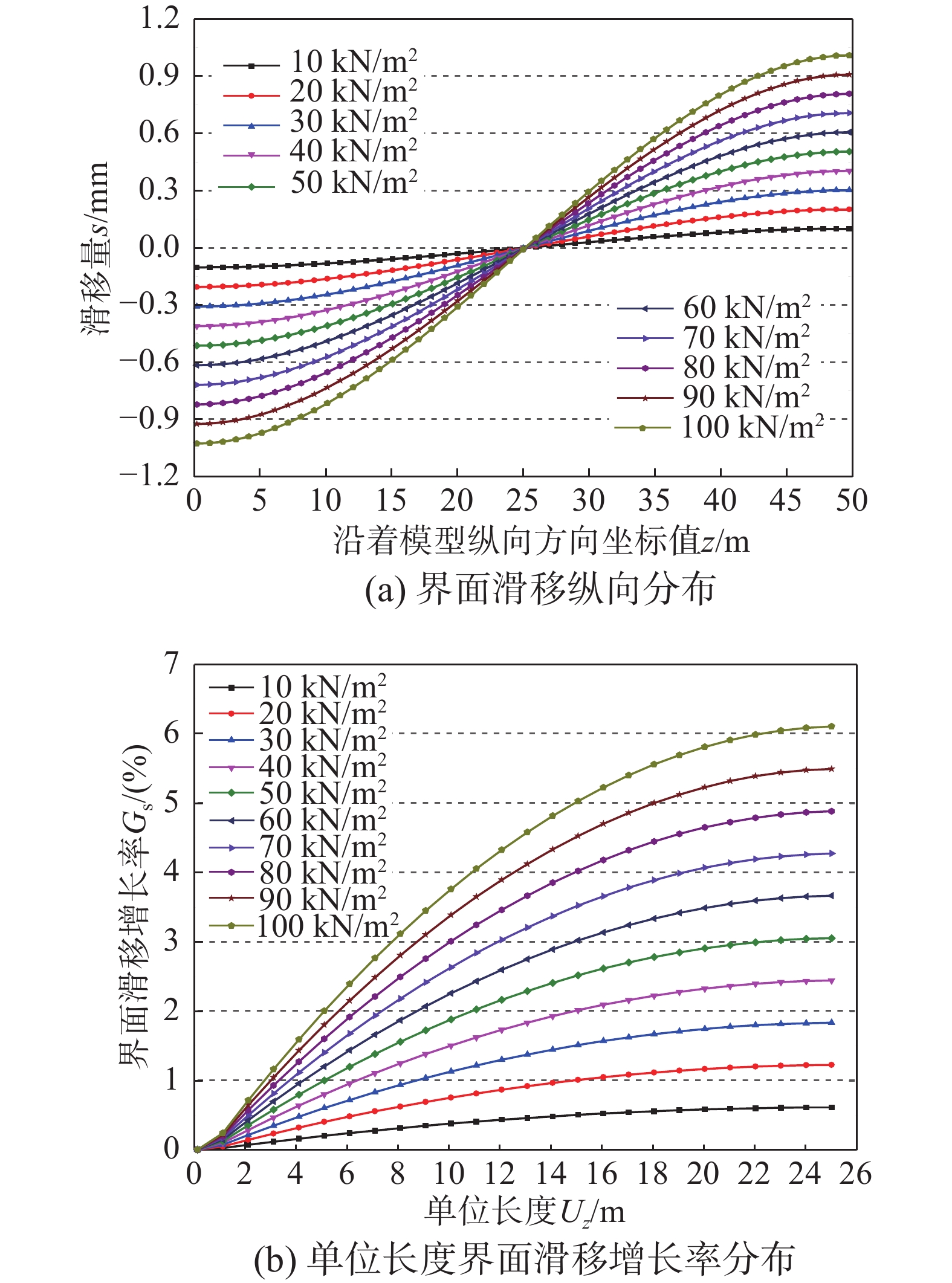
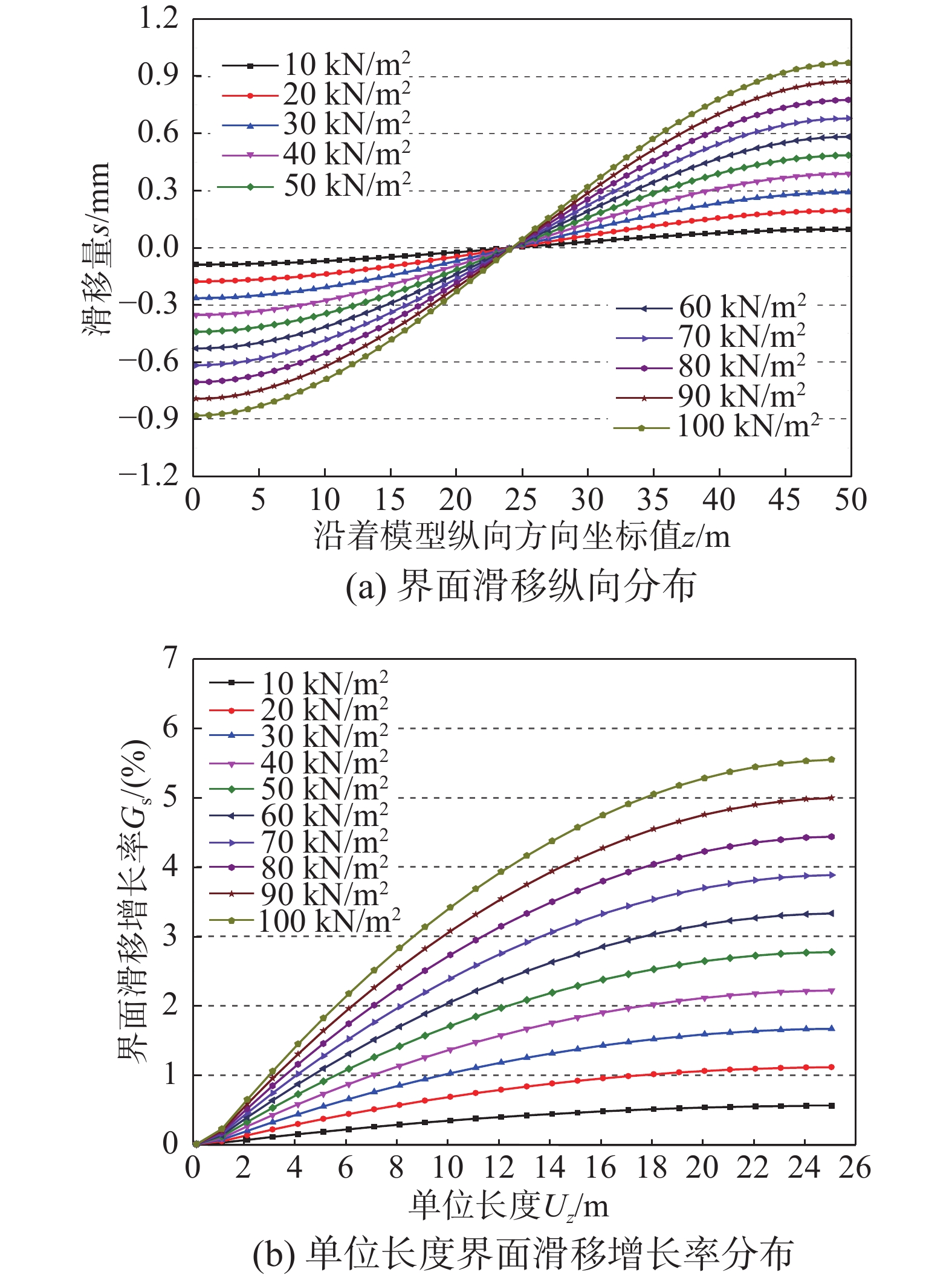
选取荷载q=10 kN/m2、20 kN/m2、30 kN/m2、40 kN/m2、50 kN/m2、60 kN/m2、70 kN/m2、80 kN/m2、90 kN/m2、100 kN/m2为特征荷载值,分别代入式(29),进行四种分析模式下的高性能箱型复合结构增韧模型界面滑移特征分析,如图8~图11所示。
![]() 图 8 I型增韧模型界面滑移韧性特征Figure 8. Interfacial slip characteristics of the toughening model with type-I concrete slab
图 8 I型增韧模型界面滑移韧性特征Figure 8. Interfacial slip characteristics of the toughening model with type-I concrete slab![]() 图 9 II型增韧模型界面滑移韧性特征Figure 9. Interfacial slip characteristics of the toughening model with type-II concrete slab
图 9 II型增韧模型界面滑移韧性特征Figure 9. Interfacial slip characteristics of the toughening model with type-II concrete slab![]() 图 10 III型增韧模型界面滑移韧性特征Figure 10. Interfacial slip characteristics of the toughening model with type-III concrete slab
图 10 III型增韧模型界面滑移韧性特征Figure 10. Interfacial slip characteristics of the toughening model with type-III concrete slab![]() 图 11 IV型增韧模型界面滑移韧性特征Figure 11. Interfacial slip characteristics of the toughening model with type-IV concrete slab
图 11 IV型增韧模型界面滑移韧性特征Figure 11. Interfacial slip characteristics of the toughening model with type-IV concrete slab由图8~图11分析表明:对于四种不同分析模型,界面滑移沿着模型纵向方向均呈现反对称分布规律。其中,跨中位置处(z=25 m)界面滑移量均为0 mm,界面滑移量向模型的两端部逐渐增大,在端部达到最大值。伴随着均布荷载q从10 kN/m2增加到100 kN/m2的过程中,界面滑移量呈现线性增长趋势,与实际情况吻合,进一步验证了界面滑移模型的正确性和通用性。
选取图8~图11中四种分析模式下不同均布荷载值(10 kN/m2~100 kN/m2)对应的端部最大滑移量smax进行比较分析,如图12所示。
![]() 图 12 四种类型增韧模型界面最大滑移量对比特征Figure 12. Comparative characteristics of the maximum interfacial slippage of the four types of toughening model
图 12 四种类型增韧模型界面最大滑移量对比特征Figure 12. Comparative characteristics of the maximum interfacial slippage of the four types of toughening model由图12分析表明,对于四种类型的高性能箱型复合结构增韧模型而言,不同均布荷载作用下,界面滑移量呈现如下关系:II型>III型>I型>IV型,表明II型高性能箱型复合结构增韧模型更具有协调适应性,韧性更强,为该种模型的韧性优化计算与分析提供了参数支持。
3.2 剪力滞韧性空间分布特性
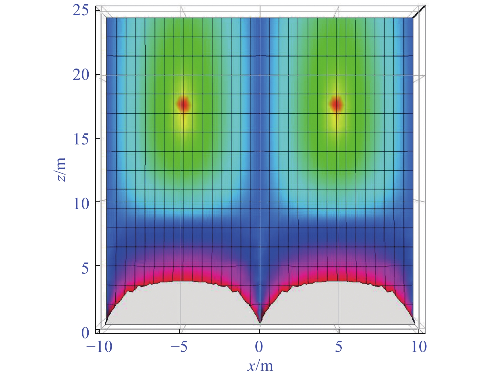
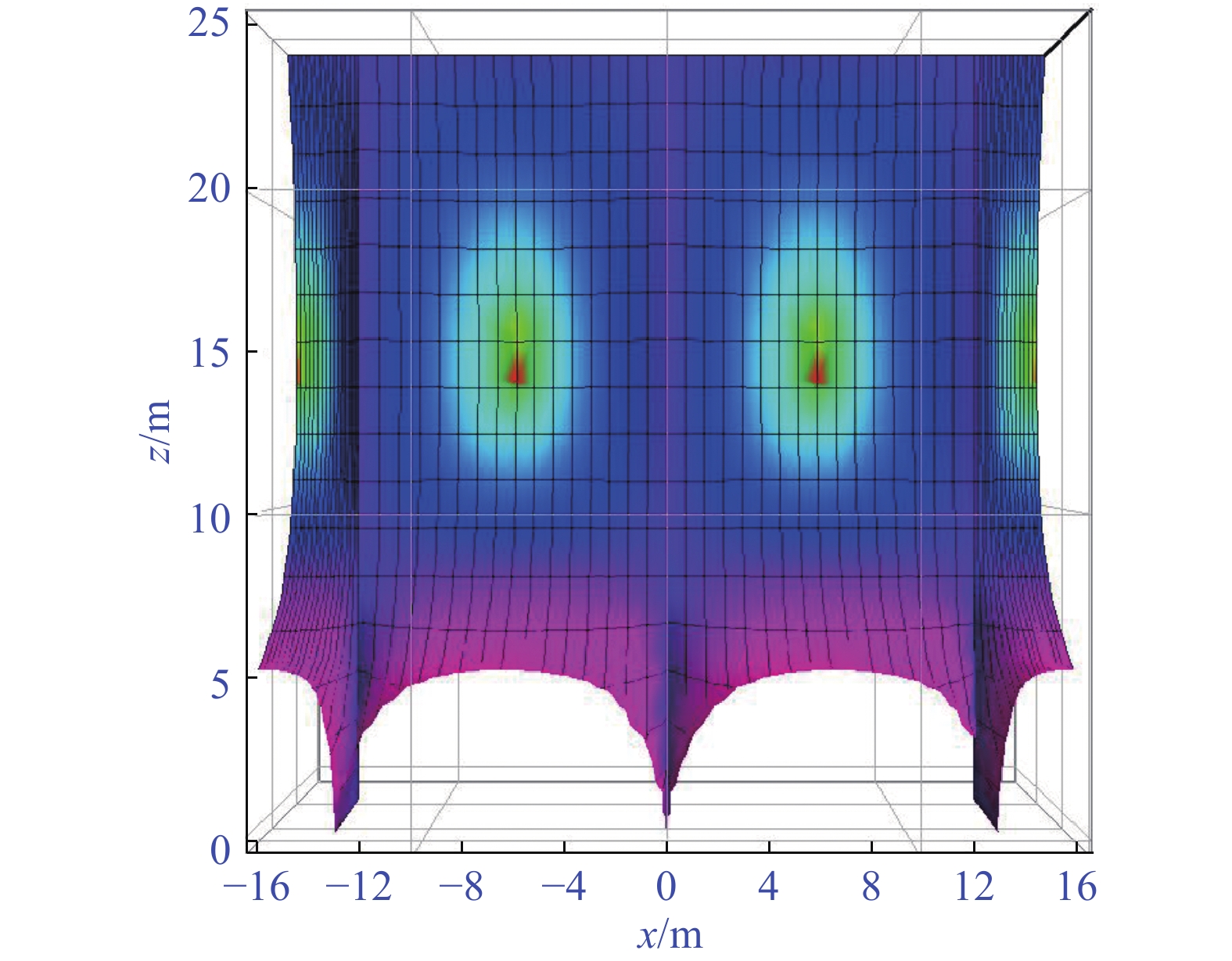
将表1中高性能箱型复合结构增韧模型四种类型的分析参数分别代入式(34)~式(36),得到四种模式下的混凝土翼板剪力滞空间分布特征和钢梁底板剪力滞空间分布特征,如图13~图20所示。
![]() 图 13 I型混凝土翼板剪力滞韧性空间分布特征Figure 13. Space distribution features of shear lag of type-I concrete slab of the toughening model
图 13 I型混凝土翼板剪力滞韧性空间分布特征Figure 13. Space distribution features of shear lag of type-I concrete slab of the toughening model![]() 图 14 I型钢梁底板剪力滞韧性空间分布特征Figure 14. Space distribution features of shear lag of bottom-plate of type-I steel girder of the toughening model
图 14 I型钢梁底板剪力滞韧性空间分布特征Figure 14. Space distribution features of shear lag of bottom-plate of type-I steel girder of the toughening model![]() 图 15 II型混凝土翼板剪力滞韧性空间分布特征Figure 15. Space distribution features of shear lag of type-II concrete slab of the toughening model
图 15 II型混凝土翼板剪力滞韧性空间分布特征Figure 15. Space distribution features of shear lag of type-II concrete slab of the toughening model![]() 图 16 II型钢梁底板剪力滞韧性空间分布特征Figure 16. Space distribution features of shear lag of bottom-plate of type-II steel girder of the toughening model
图 16 II型钢梁底板剪力滞韧性空间分布特征Figure 16. Space distribution features of shear lag of bottom-plate of type-II steel girder of the toughening model![]() 图 17 III型混凝土翼板剪力滞韧性空间分布特征Figure 17. Space distribution features of shear lag of type-III concrete slab of the toughening model
图 17 III型混凝土翼板剪力滞韧性空间分布特征Figure 17. Space distribution features of shear lag of type-III concrete slab of the toughening model![]() 图 18 III型钢梁底板剪力滞韧性空间分布特征Figure 18. Space distribution features of shear lag of bottom-plate of type-III steel girder of the toughening model
图 18 III型钢梁底板剪力滞韧性空间分布特征Figure 18. Space distribution features of shear lag of bottom-plate of type-III steel girder of the toughening model![]() 图 19 IV型混凝土翼板剪力滞韧性空间分布特征Figure 19. Space distribution features of shear lag of type-IV concrete slab of the toughening model
图 19 IV型混凝土翼板剪力滞韧性空间分布特征Figure 19. Space distribution features of shear lag of type-IV concrete slab of the toughening model![]() 图 20 IV型钢梁底板剪力滞韧性空间分布特征Figure 20. Space distribution features of shear lag of bottom-plate of type-IV steel girder of the toughening model
图 20 IV型钢梁底板剪力滞韧性空间分布特征Figure 20. Space distribution features of shear lag of bottom-plate of type-IV steel girder of the toughening model3.3 韧性优化分析
基于图13~图20中四种模式下的剪力滞空间分布特征,从混凝土翼板模式和混凝土材料2部分分别来进行高性能箱型复合结构增韧模型的性能优化分析。
1)混凝土翼板模式优化
为了精确找到剪力滞沿着梁纵向分布特征,令x=b1/2=6.5 m,代入式(34)~式(36),得到四种模式下混凝土顶翼板的剪力滞系数纵向分布曲线关系,如图21所示。
![]() 图 21 四种类型混凝土翼板剪力滞纵向分布(x=6.5 m)Figure 21. Longitudinal distributions of shear lag of four types of the toughening models (x=6.5 m)
图 21 四种类型混凝土翼板剪力滞纵向分布(x=6.5 m)Figure 21. Longitudinal distributions of shear lag of four types of the toughening models (x=6.5 m)由图21分析表明:当z=15.078 m时,混凝土翼板剪力滞系数达到最小值,四种类型混凝土翼板模式对应的剪力滞系数分别为:\lambda _{\text{1}}^{(1)} = 0.{\text{981 }}0{\text{6}},\lambda _{\text{1}}^{(2)} = 0.{\text{999 55}},\lambda _{\text{1}}^{(3)} = 0.{\text{996 27}},\lambda _{\text{1}}^{(4)} = 0.{\text{995 44}},其中,\lambda _{\text{1}}^{(2)}为4者中最大值。
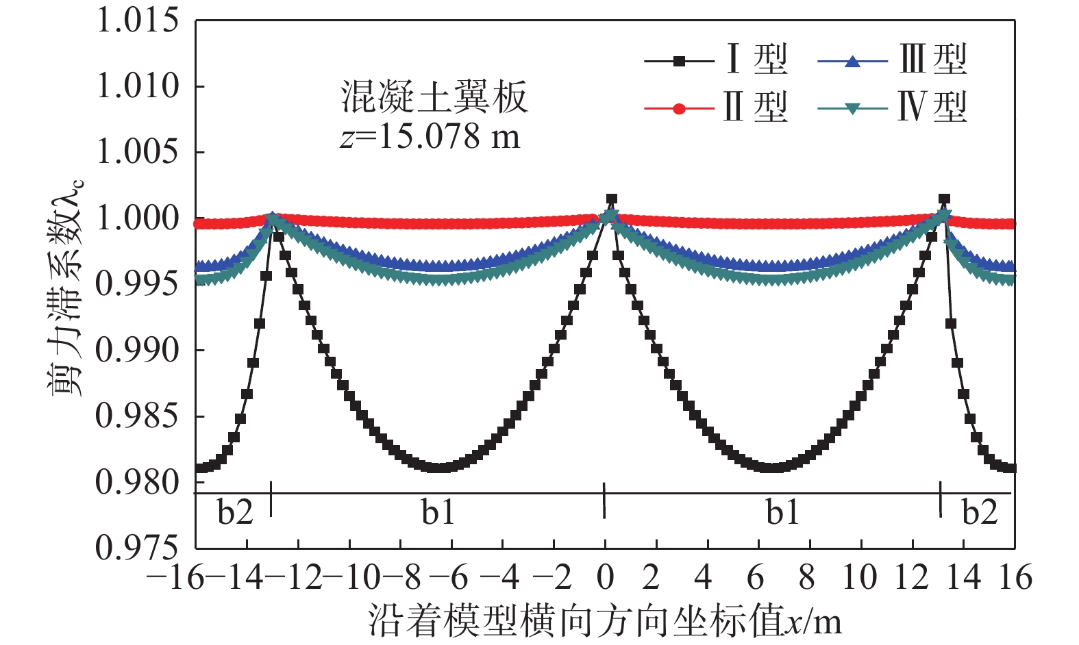
因此,得到基于剪力滞行为的四种类型高性能箱型复合结构增韧模型优化分析如图22和图23所示,优化结果见表2。
![]() 图 22 基于剪力滞行为的四种类型混凝土翼板韧性优化分析Figure 22. Optimized analysis for four types of concrete slabs based on shear lag
图 22 基于剪力滞行为的四种类型混凝土翼板韧性优化分析Figure 22. Optimized analysis for four types of concrete slabs based on shear lag![]() 图 23 基于剪力滞行为的四种类型钢梁底板韧性优化分析Figure 23. Optimized analysis for four types of steel girders based on shear lag表 2 高性能箱型复合结构增韧模型韧性优化结果Table 2. Performance optimization for the the toughening model
图 23 基于剪力滞行为的四种类型钢梁底板韧性优化分析Figure 23. Optimized analysis for four types of steel girders based on shear lag表 2 高性能箱型复合结构增韧模型韧性优化结果Table 2. Performance optimization for the the toughening model类别 C80混凝土材料 最小剪力滞系数{\lambda _{\min }} 密度{\rho _{\text{c}}}/
(kg/m3)截面面
积Ac/m2单位长度质
量\overline m/(kg/m)节约贡
献/(%)混凝土
翼板影响程
度/(%)钢梁
底板影响程
度/(%)I型 2450 16.00 39200.0 0.00 0.98106 1.89 0.94288 5.71 II型 10.40 25480.0 35.00 0.99955 0.04 0.99951 0.05 III型 12.27 30061.5 23.31 0.99627 0.37 0.99334 0.67 IV型 14.93 36578.5 6.69 0.99544 0.46 0.98606 1.39 通过图22对比分析表明,对于四种模式下的混凝土翼板,受剪力滞影响的强弱程度分别为I型>IV型>III型>II型。由图23分析表明,四种模式下的钢梁底板受剪力滞影响的强弱程度同样是I型>IV型>III型>II型。进一步由表3分析可知,采用II型高性能箱型复合结构增韧模型,剪力滞影响程度仅为0.04%~0.05%,而且节约混凝土材料用量比达35.00%。综合表明:II型高性能箱型复合结构增韧模型受剪力滞行为影响最弱,且节约成本,为四种模式中基于剪力滞行为的混凝土翼板韧性最优模型。
表 3 箱型复合结构增韧模型韧性优化材料表Table 3. Material parameters on performance optimization for the toughening model材料名称 强度等级 等级名称 密度ρc/
(kg/m3)弹性模量
Ec/GPa剪切模量
Gc/GPa混凝土材料 普通性能 C15 2400 22.0 8.8 C40 2430 32.5 13.0 高性能 C60 2450 36.0 14.4 C80 2490 39.0 15.6 2)混凝土材料性能优化
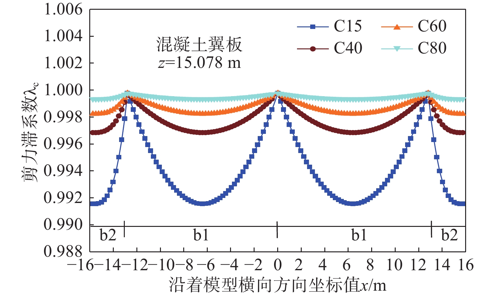
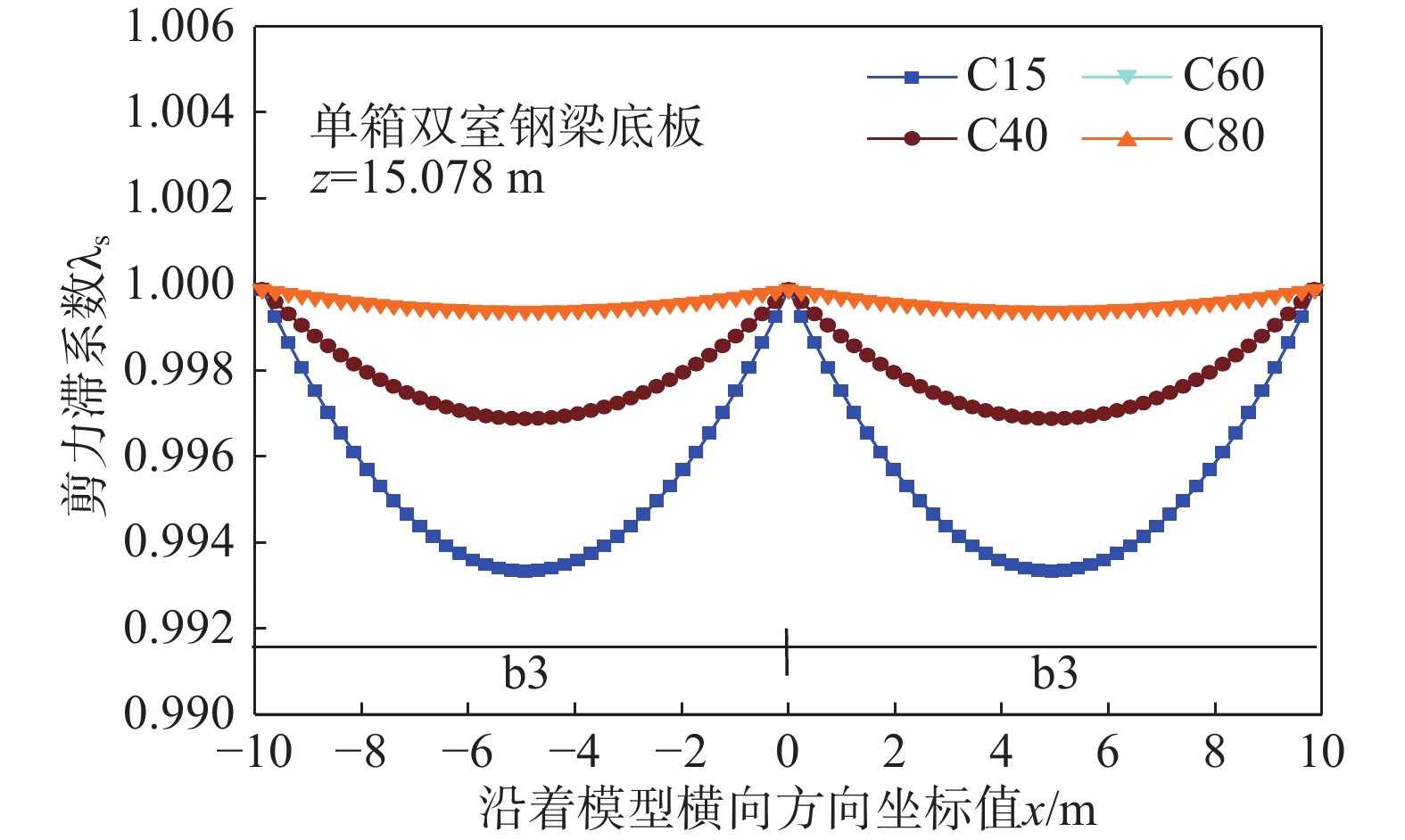
通过四种类型的普通性能混凝土(C15、C40)和高性能混凝土(C60、C80),选取基于剪力滞行为的混凝土翼板优化模型(II型)进行混凝土材料优化研究,优化分析参数见表3。得到的不同等级混凝土材料优化分析如图24和图25所示。
![]() 图 24 基于混凝土材料的II型混凝土翼板韧性对比Figure 24. Optimized comparison for type-II concrete slab based on concrete materials
图 24 基于混凝土材料的II型混凝土翼板韧性对比Figure 24. Optimized comparison for type-II concrete slab based on concrete materials![]() 图 25 基于混凝土材料的II型钢梁底板韧性对比Figure 25. Comparison of toughness of type-II bottom-plate of steel girder based on concrete materials
图 25 基于混凝土材料的II型钢梁底板韧性对比Figure 25. Comparison of toughness of type-II bottom-plate of steel girder based on concrete materials由图24和图25分析表明:对于II型高性能箱型复合结构增韧模型,剪力滞系数随着混凝土强度的增加,剪力滞行为对II型模型中混凝土翼板和钢梁底板的影响逐渐减弱。对于普通性能混凝土而言,剪力滞减弱程度十分显著;而对于高性能混凝土,减弱程度较弱或影响程度并不显著。
4 结论
基于建立的剪力滞与界面滑移耦合模型,提出了高性能箱型复合结构增韧模型与计算理论,并以界面滑移量、剪力滞系数、混凝土材料为韧性敏感参数,对高性能箱型复合结构增韧模型进行了界面滑移韧性特征、剪力滞韧性空间分布特性及韧性优化理论分析,结论如下:
(1)提出了考虑剪力滞行为与界面滑移的耦合分析方法,求解出基于界面滑移和剪力滞系数的韧性解析解,实现了高性能箱型复合结构增韧模型韧性行为精确分析与计算。
(2)通过均布荷载作用下的算例分析得到了高性能箱型复合结构增韧模型的界面滑移韧性特征与剪力滞韧性空间分布特性,分析了四种模式下不同荷载等级对其韧性性能的影响机理,为韧性优化分析提供了参数支持。
(3)以四种混凝土翼板模式和普通性能、高性能混凝土材料为韧性优化因子,得到了文中II型高性能箱型复合结构增韧模型受剪力滞影响程度仅为0.04%~0.05%,混凝土材料用量节约35.00%的增韧结论,确定了基于剪力滞与界面滑移耦合行为的最优化箱型复合结构增韧模型。
-
![]()
图 8 I型增韧模型界面滑移韧性特征
Figure 8. Interfacial slip characteristics of the toughening model with type-I concrete slab
![]()
图 9 II型增韧模型界面滑移韧性特征
Figure 9. Interfacial slip characteristics of the toughening model with type-II concrete slab
![]()
图 10 III型增韧模型界面滑移韧性特征
Figure 10. Interfacial slip characteristics of the toughening model with type-III concrete slab
![]()
图 11 IV型增韧模型界面滑移韧性特征
Figure 11. Interfacial slip characteristics of the toughening model with type-IV concrete slab
![]()
图 12 四种类型增韧模型界面最大滑移量对比特征
Figure 12. Comparative characteristics of the maximum interfacial slippage of the four types of toughening model
![]()
图 13 I型混凝土翼板剪力滞韧性空间分布特征
Figure 13. Space distribution features of shear lag of type-I concrete slab of the toughening model
![]()
图 14 I型钢梁底板剪力滞韧性空间分布特征
Figure 14. Space distribution features of shear lag of bottom-plate of type-I steel girder of the toughening model
![]()
图 15 II型混凝土翼板剪力滞韧性空间分布特征
Figure 15. Space distribution features of shear lag of type-II concrete slab of the toughening model
![]()
图 16 II型钢梁底板剪力滞韧性空间分布特征
Figure 16. Space distribution features of shear lag of bottom-plate of type-II steel girder of the toughening model
![]()
图 17 III型混凝土翼板剪力滞韧性空间分布特征
Figure 17. Space distribution features of shear lag of type-III concrete slab of the toughening model
![]()
图 18 III型钢梁底板剪力滞韧性空间分布特征
Figure 18. Space distribution features of shear lag of bottom-plate of type-III steel girder of the toughening model
![]()
图 19 IV型混凝土翼板剪力滞韧性空间分布特征
Figure 19. Space distribution features of shear lag of type-IV concrete slab of the toughening model
![]()
图 20 IV型钢梁底板剪力滞韧性空间分布特征
Figure 20. Space distribution features of shear lag of bottom-plate of type-IV steel girder of the toughening model
![]()
图 21 四种类型混凝土翼板剪力滞纵向分布(x=6.5 m)
Figure 21. Longitudinal distributions of shear lag of four types of the toughening models (x=6.5 m)
![]()
图 22 基于剪力滞行为的四种类型混凝土翼板韧性优化分析
Figure 22. Optimized analysis for four types of concrete slabs based on shear lag
![]()
图 23 基于剪力滞行为的四种类型钢梁底板韧性优化分析
Figure 23. Optimized analysis for four types of steel girders based on shear lag
![]()
图 24 基于混凝土材料的II型混凝土翼板韧性对比
Figure 24. Optimized comparison for type-II concrete slab based on concrete materials
![]()
图 25 基于混凝土材料的II型钢梁底板韧性对比
Figure 25. Comparison of toughness of type-II bottom-plate of steel girder based on concrete materials
表 1 均布荷载作用下高性能箱型复合结构增韧模型分析参数一览表
Table 1 Analysis parameters of the toughening model under uniformly distributed loading
分析模式 混凝土
翼板截面
面积
{A_{\text{c}}} /m2钢截面
面积
{A_{\text{s}}} /m2模型型心
到坐标
原点的距离
{y_0} /m混凝土
翼板型心
到坐标
原点的距离
{y_{\text{1}}} = {y_{\text{2}}} = {y_{\text{c}}} /m钢梁底板
型心
到坐标
原点的距离
{y_{\text{3}}} = {y_{{\text{sb}}}} /m钢梁托板
型心
到坐标
原点的距离
{y_4} = {y_{{\text{st}}}} /m钢梁腹板
型心
到坐标
原点的距离
{y_5} = {y_{{\text{sw}}}} /m混凝土
翼板截面
惯性矩
{I_{\text{c}}} /m4钢梁截面
惯性矩
{I_{\text{s}}} /m4中间量
{d_{{\text{cs}}}} /mI型 16.00 1.525 0.3723 −0.1223 +1.8277 −0.1527 +1.0277 0.5727 3.6275 1.5057 II型 10.40 1.525 0.3780 −0.1998 +1.7219 −0.1469 +0.9219 1.3284 3.2053 1.4775 III型 12.27 1.525 0.3756 −0.1698 +1.7244 −0.1493 +0.9243 2.0438 3.2149 1.4499 IV型 14.93 1.525 0.3757 −0.1307 +1.7243 −0.1493 +0.9243 3.7632 3.2145 1.4107 分析模式 中间量
{d_{\text{c}}} /m中间量
{d_{\text{s}}} /m中间量
{d_{\text{d}}}/m剪力键刚度
K/(N/m)中间量{\pi _0} 中间量{\pi _1} 中间量\overline \pi 中间量\varpi 中间量{\kappa _1} 中间量{\kappa _2} I型 0.5042 1.0015 0.016 68545 0.0007 0.0165 0.0067 0.1972 0.0010 0.0042 II型 0.6684 0.8091 0.016 68545 0.0006 0.0158 0.0082 0.2353 0.0032 0.0032 III型 0.5972 0.8526 0.016 68545 0.0006 0.0152 0.0086 0.2345 0.0025 0.0040 IV型 0.4943 0.9164 0.016 68545 0.0005 0.0146 0.0088 0.1985 0.0012 0.0037  下载: 导出CSV
表 2 高性能箱型复合结构增韧模型韧性优化结果
Table 2 Performance optimization for the the toughening model
类别 C80混凝土材料 最小剪力滞系数{\lambda _{\min }} 密度{\rho _{\text{c}}}/
(kg/m3)截面面
积Ac/m2单位长度质
量\overline m/(kg/m)节约贡
献/(%)混凝土
翼板影响程
度/(%)钢梁
底板影响程
度/(%)I型 2450 16.00 39200.0 0.00 0.98106 1.89 0.94288 5.71 II型 10.40 25480.0 35.00 0.99955 0.04 0.99951 0.05 III型 12.27 30061.5 23.31 0.99627 0.37 0.99334 0.67 IV型 14.93 36578.5 6.69 0.99544 0.46 0.98606 1.39
下载: 导出CSV
表 3 箱型复合结构增韧模型韧性优化材料表
Table 3 Material parameters on performance optimization for the toughening model
材料名称 强度等级 等级名称 密度ρc/
(kg/m3)弹性模量
Ec/GPa剪切模量
Gc/GPa混凝土材料 普通性能 C15 2400 22.0 8.8 C40 2430 32.5 13.0 高性能 C60 2450 36.0 14.4 C80 2490 39.0 15.6
下载: 导出CSV
-
[1] 聂建国. 钢-混凝土组合结构原理与实例[M]. 北京: 科学出版社, 2009: 6 − 15. NIE Jianguo. Composite structures of steel and concrete: Theory and practice [M]. Beijing: Science Press, 2009: 6 − 15. (in Chinese)
[2] 舒小娟, 钟新谷, 沈明燕, 等. 钢箱-混凝土组合梁初步设计与应用[J]. 土木工程学报, 2011, 44(增刊1): 8 − 16, 37. SHU Xiaojuan, ZHONG Xingu, SHEN Mingyan, et al. Preliminary design and application of steel-box concrete composite beam [J]. China Civil Engineering Journal, 2011, 44(Suppl 1): 8 − 16, 37. (in Chinese)
[3] 刘沐宇, 李倩, 黄岳斌, 等. 港珠澳大桥钢-混组合连续梁桥超长时间收缩徐变效应[J]. 中国公路学报, 2016, 29(12): 60 − 69. doi: 10.3969/j.issn.1001-7372.2016.12.008 LIU Muyu, LI Qian, HUANG Yuebin, et al. Ultra-long time performance of steel-concrete composite continuous beam in Hong Kong-Zhuhai-Macao bridge with creep and shrinkage of concrete slabs [J]. China Journal of Highway and Transport, 2016, 29(12): 60 − 69. (in Chinese) doi: 10.3969/j.issn.1001-7372.2016.12.008
[4] 聂建国, 李盛勇, 刘嵘, 等. 深圳华润中心月牙形中庭大跨钢-混凝土组合结构[J]. 建筑结构学报, 2004, 25(6): 126 − 128. NIE Jianguo, LI Shengyong, LIU Rong, et al. Long-span steel-concrete composite structure of the crescent hall of Shenzhen Huarun center [J]. Journal of Building Structures, 2004, 25(6): 126 − 128. (in Chinese)
[5] YASSIN A Y M, NETHERCOT D A. Cross-sectional properties of complex composite beams [J]. Engineering Structures, 2007, 29(2): 195 − 212. doi: 10.1016/j.engstruct.2006.04.010
[6] SA-NGUANMANASAK J, CHAISOMPHOB T, YAMAGUCHI E. Stress concentration due to shear lag in continuous box girders [J]. Engineering Structures, 2007, 29(7): 1414 − 1421. doi: 10.1016/j.engstruct.2006.08.010
[7] 孙飞飞, 李国强. 考虑滑移、剪力滞后和剪切变形的钢-混凝土组合梁解析解[J]. 工程力学, 2005, 22(2): 96 − 103. SUN Feifei, LI Guoqiang. A closed-form solution for steel-concrete composite beams with slip, shear lag and shear deformation [J]. Engineering Mechanics, 2005, 22(2): 96 − 103. (in Chinese)
[8] 李法雄, 聂建国. 钢-混凝土组合梁剪力滞效应弹性解析解[J]. 工程力学, 2011, 28(9): 1 − 8. LI Faxiong, NIE Jianguo. Elastic analytical solutions of shear lag effect of steel-concrete composite beam [J]. Engineering Mechanics, 2011, 28(9): 1 − 8. (in Chinese)
[9] 程海根, 强士中. 钢-混凝土组合箱梁剪力滞效应级数解[J]. 土木工程学报, 2004, 37(9): 37 − 40. doi: 10.3321/j.issn:1000-131X.2004.09.007 CHENG Haigen, QIANG Shizhong. Series solution of shear lag of steel-concrete composite box girder [J]. China Civil Engineering Journal, 2004, 37(9): 37 − 40. (in Chinese) doi: 10.3321/j.issn:1000-131X.2004.09.007
[10] 何余良, 项贻强, 李少俊, 等. 基于不同抛物线翘曲函数组合箱梁剪力滞[J]. 浙江大学学报(工学版), 2014, 48(11): 1933 − 1940, 1961. HE Yuliang, XIANG Yiqiang, LI Shaojun, et al. Analysis on shear-lag effect of composite girders based on different parabolic warping displacement function [J]. Journal of Zhejiang University (Engineering Science), 2014, 48(11): 1933 − 1940, 1961. (in Chinese)
[11] 朱力, 聂建国, 季文玉. 钢—混凝土组合箱型梁的滑移和剪力滞效应[J]. 工程力学, 2016, 33(9): 49 − 58, 68. doi: 10.6052/j.issn.1000-4750.2015.05.0562 ZHU Li, NIE Jianguo, JI Wenyu. Slip and shear-lag effects of steel-concrete composite box beam [J]. Engineering Mechanics, 2016, 33(9): 49 − 58, 68. (in Chinese) doi: 10.6052/j.issn.1000-4750.2015.05.0562
[12] 胡少伟, 喻江, 张文敬. 集中荷载作用下宽翼缘双箱组合梁剪滞效应分析[J]. 工程力学, 2015, 32(5): 120 − 130. doi: 10.6052/j.issn.1000-4750.2013.11.1078 HU Shaowei, YU Jiang, ZHANG Wenjing. Analysis of shear lag effect in double-box composite beams with wide flanges under concentrated loading [J]. Engineering Mechanics, 2015, 32(5): 120 − 130. (in Chinese) doi: 10.6052/j.issn.1000-4750.2013.11.1078
[13] HU S W, YU J, HUANG Y Q, et al. Theoretical and experimental investigations on shear lag effect of double-box composite beam with wide flange under symmetrical loading [J]. Journal of Mechanics, 2015, 31(6): 653 − 663. doi: 10.1017/jmech.2015.31
[14] 周世军, 黄瑜, 江瑶, 等. 单箱双室组合箱梁剪力滞效应分析[J]. 建筑科学与工程学报, 2017, 34(6): 110 − 115. doi: 10.3969/j.issn.1673-2049.2017.06.015 ZHOU Shijun, HUANG Yu, JIANG Yao, et al. Analysis of shear lag effect of single-box twin-cell composite box girder [J]. Journal of Architecture and Civil Engineering, 2017, 34(6): 110 − 115. (in Chinese) doi: 10.3969/j.issn.1673-2049.2017.06.015
[15] YU J, HU S W, ZHANG Z G, et al. Shear lag and related parameter impact researches for twin-cell composite box beam under concentrated loads [J]. Journal of Mechanics, 2017, 33(4): 443 − 460. doi: 10.1017/jmech.2017.5
[16] 缪惠全, 钟紫蓝, 侯本伟, 等. 基于系统动力学的城市供水管网动态抗震韧性评估方法[J]. 工程力学, 2023, 40(12): 99 − 112. doi: 10.6052/j.issn.1000-4750.2022.02.0154 MIAO Huiquan, ZHONG Zilan, HOU Benwei, et al. Dynamic seismic resilience assessment method for water distribution networks based on system dynamics [J]. Engineering Mechanics, 2023, 40(12): 99 − 112. (in Chinese) doi: 10.6052/j.issn.1000-4750.2022.02.0154
[17] 庄亮东, 杨悦, 吴桢灏. 遗传算法在Y型偏心支撑组合框架抗震性能优化中的应用研究[J]. 工程力学, 2023, 40(7): 185 − 195. doi: 10.6052/j.issn.1000-4750.2021.11.0934 ZHUANG Liangdong, YANG Yue, WU Zhenhao. The application of genetic algorithm in seismic performance optimization of y-shape eccentrically braced composite frame [J]. Engineering Mechanics, 2023, 40(7): 185 − 195. (in Chinese) doi: 10.6052/j.issn.1000-4750.2021.11.0934
[18] 杨松, 陈钒, 齐兵, 等. 钢-超高性能混凝土组合箱梁静力性能试验研究与数值模拟[J]. 工程力学, 2022, 39(8): 88 − 102. doi: 10.6052/j.issn.1000-4750.2021.04.0290 YANG Song, CHEN Fan, QI Bing, et al. Experimental and numerical research on static performance of steel-uhpc composite box girder [J]. Engineering Mechanics, 2022, 39(8): 88 − 102. (in Chinese) doi: 10.6052/j.issn.1000-4750.2021.04.0290
[19] ECSEDI I, BAKSA A. Analytical solution for layered composite beams with partial shear interaction based on timoshenko beam theory [J]. Engineering Structures, 2016, 115: 107 − 117. doi: 10.1016/j.engstruct.2016.02.034
[20] JGJ 138−2016, 组合结构设计规范[S]. 北京: 中国建筑工业出版社, 2016. JGJ 138−2016, Code for design of composite structures [S]. Beijing: China Architecture & Building Press, 2016. (in Chinese)
[21] JTG D64−2015, 公路钢结构桥梁设计规范[S]. 北京: 人民交通出版社, 2015. JTG D64−2015, Specifications for design of highway steel bridge [S]. Beijing: China Communication Press, 2015. (in Chinese)


计量
- 文章访问数: 112
- HTML全文浏览量: 32
- PDF下载量: 13
